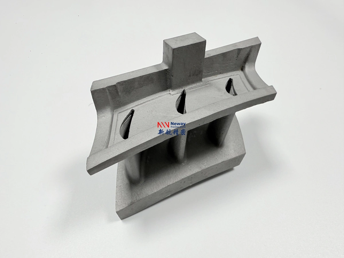
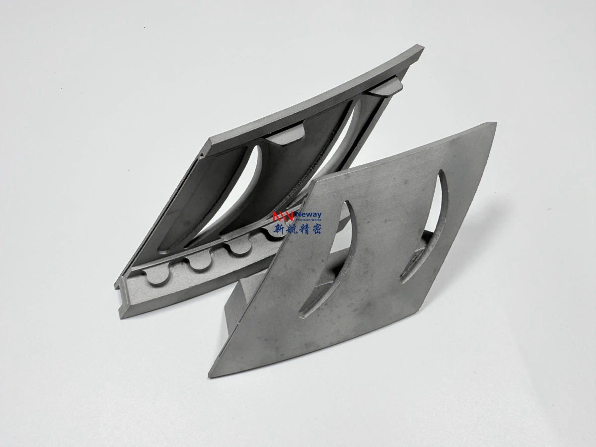
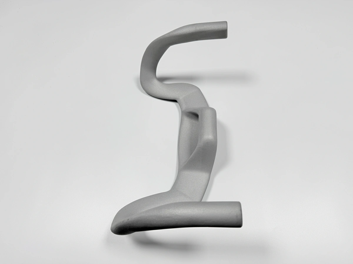
Post-Processing for 3D Printed Superalloy Parts: Heat Treatment, HIP, CNC, EDM, and Inspection
For high-temperature aerospace, turbine, combustion, energy, and industrial applications, metal 3D printing is usually only the first manufacturing step. Most superalloy 3D printing projects require a complete post-processing workflow before the parts are ready for assembly, testing, or functional use.
Superalloy printed parts often need support removal, stress relief, heat treatment, HIP evaluation, CNC machining, EDM, surface finishing, and inspection documentation. This is especially important for Inconel 718, Inconel 625, Hastelloy X, Haynes 188, Inconel 713C, and other high-temperature alloys used in severe environments.
For buyers, the key point is simple: a 3D printed superalloy part should not be evaluated only by printing cost. The final cost, lead time, and quality depend heavily on what happens after printing. A finished superalloy component usually requires controlled post-processing and clear inspection planning.
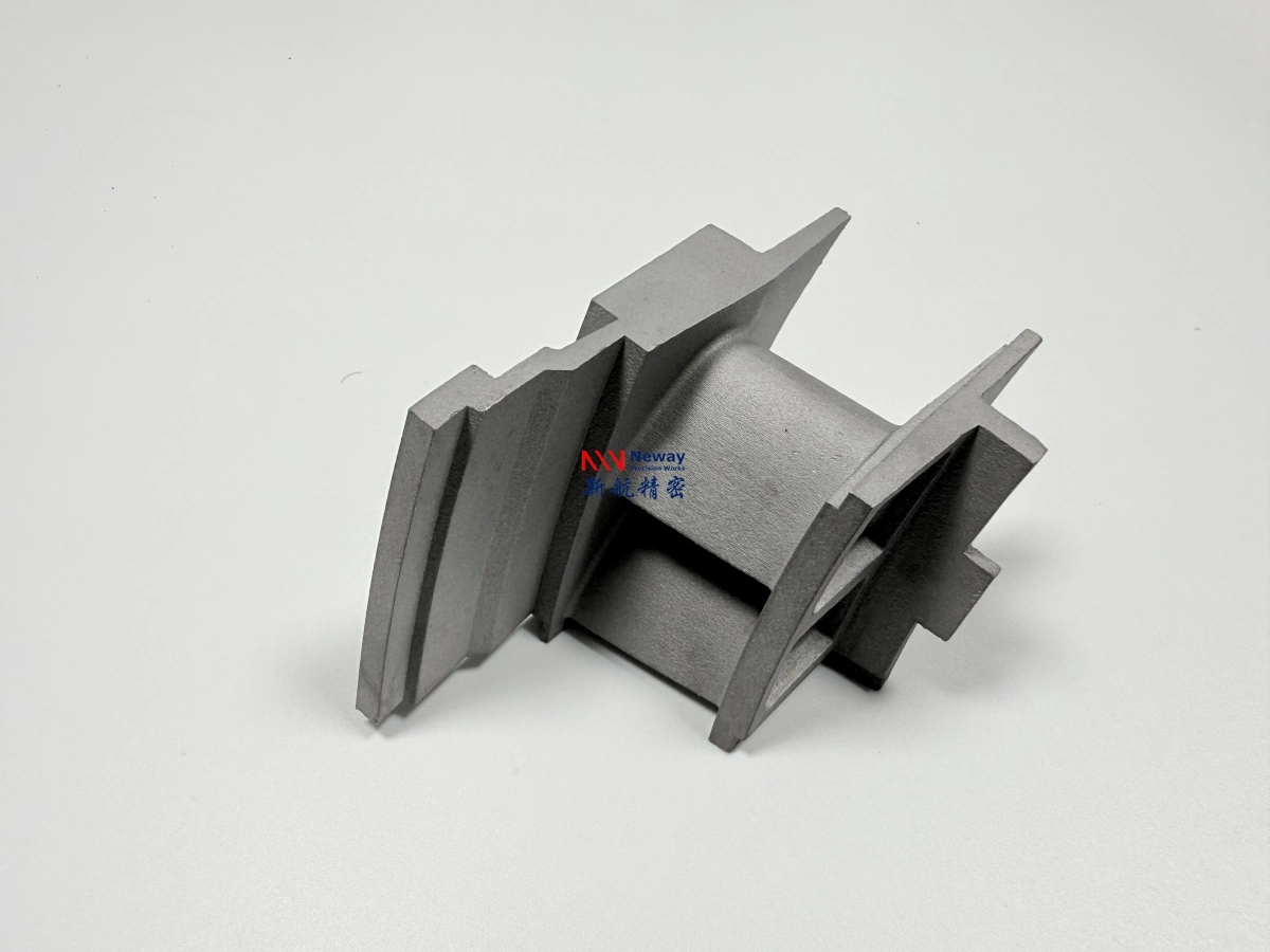
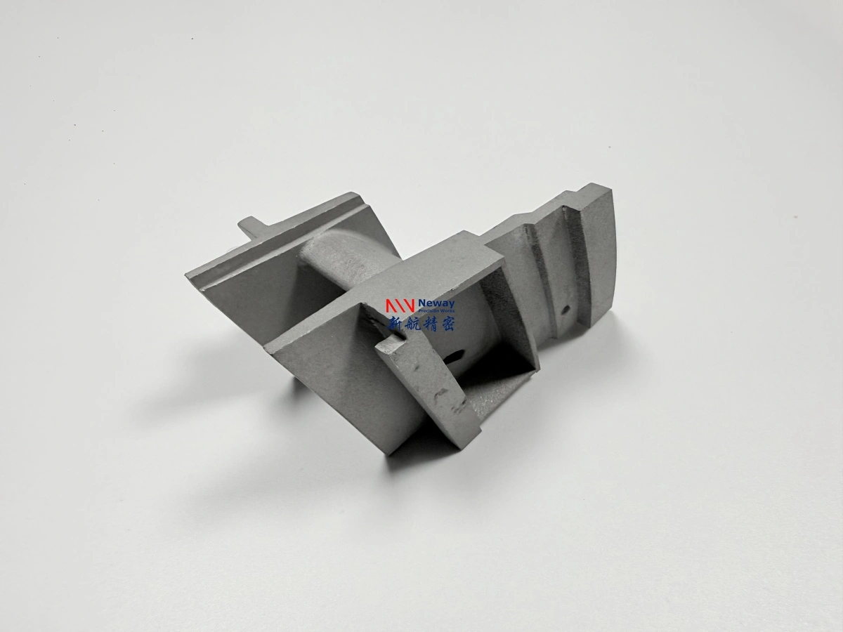
Why Post-Processing Is Required for Superalloy 3D Printed Parts
Superalloy parts are usually selected for demanding working conditions such as high temperature, oxidation, corrosion, thermal cycling, load, vibration, or fatigue. These requirements cannot be met reliably by printing alone in many projects.
Post-processing is required because metal powder bed fusion may leave residual stress, as-printed surface roughness, support marks, internal porosity risk, dimensional deviation, and unfinished functional surfaces. For high-value parts, these issues must be controlled before delivery.
Common reasons for post-processing include:
Reducing residual stress after printing
Improving material stability through heat treatment
Reducing internal defect risk through HIP evaluation
Removing support structures without damaging thin walls
Machining sealing faces, mounting surfaces, holes, and threads
Using EDM for narrow slots, deep features, or complex superalloy details
Improving surface condition through blasting, polishing, or deburring
Verifying dimensions, internal quality, and process traceability
For aerospace and turbine components, post-processing should be defined at the RFQ stage. This helps avoid misunderstandings about whether the supplier is quoting an as-printed part or a finished, inspected engineering component.
Support Removal After Superalloy 3D Printing
Support removal is often the first major post-processing step after printing. Supports are needed to stabilize overhangs, conduct heat, reduce deformation, and improve build success. However, they can also create surface marks, removal difficulty, and risk for thin-wall structures.
Support removal should be planned together with build orientation and part geometry. If supports are placed on critical sealing faces, gas-flow surfaces, thin airfoil edges, or cosmetic surfaces, additional machining or finishing may be required.
Support removal risks include:
Damage to thin walls or delicate edges
Surface defects in support contact areas
Deformation during mechanical removal
Unreachable supports inside complex cavities
Extra polishing or machining cost after removal
For complex turbine vanes, nozzles, heat shields, and internal-channel structures, the supplier should confirm support accessibility before production. If supports cannot be removed safely, the design or build orientation may need adjustment.
Support Area | Potential Issue | Recommended Control |
|---|---|---|
Thin-wall section | Wall deformation or edge damage | Review support density, access, and removal method |
Sealing face | Support marks and poor flatness | Reserve CNC machining allowance |
Gas-flow surface | Rough surface and flow disturbance | Avoid support contact where possible |
Internal cavity | Unreachable support or trapped powder | Redesign access or modify orientation |
Heat Treatment for 3D Printed Superalloy Parts
Heat treatment is one of the most important post-processing steps for many printed superalloy components. Depending on the material and application, heat treatment may be used for stress relief, microstructure stabilization, precipitation hardening, or performance adjustment.
For high-strength alloys such as Inconel 718, heat treatment is often essential for achieving the intended mechanical properties. For hot gas path alloys such as Hastelloy X or Haynes 188, thermal processing may be used to stabilize the part for high-temperature service. For crack-sensitive materials such as Inconel 713C, heat treatment strategy should be reviewed carefully with the overall manufacturing route.
The heat treatment plan should consider:
Material grade and powder specification
As-printed residual stress
Required mechanical properties
Operating temperature and thermal cycling conditions
Whether CNC machining will occur before or after heat treatment
Whether dimensional distortion may occur during thermal processing
Required heat treatment record or certificate
For alloy-specific post-processing examples, the workflows for Inconel 718 post-processing and Hastelloy X post-processing can help buyers understand how heat treatment, HIP, and machining are combined after printing.
HIP Evaluation for Superalloy 3D Printed Parts
Hot isostatic pressing, or HIP, may be recommended when internal integrity, fatigue performance, density improvement, or defect reduction is important. It is commonly considered for aerospace, turbine, energy, and high-reliability superalloy components.
HIP is not required for every 3D printed superalloy part. A visual prototype, simple fit-check part, or non-critical fixture may not need HIP. However, for functional turbine parts, pressure-related parts, fatigue-sensitive structures, or high-temperature test components, HIP can be an important part of the quality strategy.
HIP may be considered when the part has:
Fatigue-sensitive loading
High operating temperature
Internal porosity risk
Functional aerospace or turbine requirements
Thin-wall or complex internal structures requiring higher reliability
Customer requirements for density improvement or internal defect control
For more detailed decision support, the FAQ on HIP for superalloys explains when HIP should be included in a superalloy 3D printing workflow.
Application Type | HIP Need | Reason |
|---|---|---|
Visual or fit-check prototype | Usually optional | Main goal is geometry or assembly review |
Thermal test component | Application-dependent | Depends on temperature, load, and test severity |
Turbine or aerospace part | Often evaluated | Internal integrity and fatigue resistance may be important |
Pressure or fatigue-sensitive part | Strongly considered | Internal defect reduction may improve reliability |
CNC Machining After Superalloy 3D Printing
Most functional superalloy printed parts require CNC machining after printing. Powder bed fusion can create complex geometry, but it is not normally used to achieve precision tolerances on sealing faces, mounting surfaces, holes, threads, and datum features.
CNC machining is commonly required for:
Mounting faces and flange surfaces
Sealing surfaces and gasket contact areas
Precision holes and counterbores
Threaded features
Datum surfaces for CMM inspection
Assembly interfaces
Flatness, perpendicularity, or tight tolerance features
Machining allowance should be included during design. If critical features are printed to final size without stock allowance, it may be difficult to correct distortion, remove support marks, or achieve the required tolerance.
For superalloys, CNC machining is usually slower and more expensive than machining aluminum or stainless steel. Tool wear, work hardening, heat generation, and fixture stability should be considered when planning the part design and quotation.
EDM for Difficult Superalloy Features
Electrical discharge machining is often used when a superalloy feature is difficult, inefficient, or risky to machine by conventional cutting. EDM is especially useful for hard alloys, narrow slots, deep cavities, small holes, complex profiles, or delicate areas where tool access is limited.
EDM may be suitable for:
Deep slots and narrow grooves
Small cooling holes or difficult internal features
Complex superalloy profiles
Thin-wall areas where cutting force must be minimized
Features near turbine vane roots, nozzle structures, or gas-path geometry
For printed parts with holes, slots, threads, and precision interfaces, the FAQ on CNC or EDM features can help define which surfaces should be printed near-net and which should be finished after printing.
Surface Treatment and Finishing
As-printed superalloy surfaces are usually rougher than machined surfaces. Depending on the application, the part may require blasting, polishing, deburring, support mark removal, coating preparation, or protective surface treatment.
Surface finishing may be required for:
Reducing surface roughness
Removing support marks
Improving fit or assembly behavior
Preparing surfaces for coating
Reducing stress concentration on exposed surfaces
Improving flow behavior in accessible gas-path areas
For internal channels, finishing options may be limited. Therefore, internal surface requirements should be discussed before printing. If a cooling channel, nozzle, or flow path requires a specific roughness or pressure drop, the design and process route should be reviewed carefully.
For cobalt-based hot-section components, finishing requirements can be different from nickel alloys. The FAQ on Haynes 188 finishing provides additional guidance for thermal cycling and hot gas path applications.
Inspection for 3D Printed Superalloy Parts
Inspection is a critical part of the post-processing workflow. For aerospace, turbine, energy, and hot-section components, customers often need more than a simple visual check. Inspection may need to confirm dimensional accuracy, internal quality, surface condition, material traceability, and post-processing records.
Common inspection and documentation items include:
CMM inspection for critical dimensions and datum features
3D scanning for complex profiles and curved surfaces
X-ray inspection for internal defect screening
CT scanning for internal channels, porosity, and powder trapping
FAI report for first article dimensional confirmation
Material certificate for alloy and powder traceability
Heat treatment record for post-processing confirmation
HIP record when HIP is included in the process
The required inspection level should match the part’s function. A prototype for assembly checking may only need basic dimensional inspection. A turbine hot-section test part may require CMM, X-ray or CT, material certificate, and heat treatment documentation.
For aerospace or turbine buyers, the FAQ on inspection reports can help define quality documentation before quotation.
Inspection Item | Purpose | Typical Use Case |
|---|---|---|
CMM inspection | Checks machined datum and critical dimensions | Mounting faces, holes, sealing surfaces |
3D scanning | Checks complex surface deviation | Vanes, nozzles, curved gas-path parts |
X-ray inspection | Screens internal defect indications | Structural hot-section components |
CT scanning | Checks internal channels, porosity, and trapped powder | Cooling channels, cavities, nozzles |
FAI report | Confirms first article dimensions | Prototype validation before repeat orders |
Material certificate | Confirms alloy grade and traceability | Aerospace, turbine, and energy projects |
Heat treatment record | Confirms thermal processing condition | Functional high-temperature parts |
Material-Specific Post-Processing Considerations
Different superalloys may require different post-processing priorities. The correct workflow depends on the alloy, geometry, application, and inspection standard.
Material | Main Post-Processing Focus | Typical Application Direction |
|---|---|---|
Inconel 718 | Heat treatment, HIP evaluation, CNC machining, inspection | High-strength aerospace and energy components |
Inconel 625 | Surface finishing, corrosion-related requirements, machining | Corrosion-resistant and energy components |
Hastelloy X | Heat treatment, surface condition, thermal stability, inspection | Combustion and hot gas path components |
Haynes 188 | Support removal, thermal cycling stability, surface finishing | Cobalt-based hot-section and combustion parts |
Inconel 713C | Crack control, heat treatment strategy, HIP evaluation, CNC/EDM, inspection | Turbine vane, nozzle, and hot-section prototypes |
For crack-sensitive turbine parts, post-processing control should be discussed before printing begins. The FAQ on Inconel 713C post-processing explains why heat treatment, HIP evaluation, machining, and inspection should be planned as one workflow.
RFQ Checklist for Finished Superalloy 3D Printed Parts
To quote finished superalloy 3D printed parts accurately, the supplier needs to know the complete delivery condition. A quote for an as-printed part is very different from a quote for a heat-treated, machined, inspected, and documented component.
Please provide the following information when requesting a quote:
3D CAD file in STEP, X_T, or STL format
2D drawing with tolerances, datum references, and critical dimensions
Required material grade or acceptable alternative alloy
Quantity for prototype, validation, or small-batch production
Operating temperature, load, pressure, corrosion, or thermal cycling conditions
Required heat treatment or mechanical property target
Whether HIP is required or should be evaluated
Surfaces requiring CNC machining, EDM, polishing, coating, or deburring
Thread, hole, slot, sealing, and datum requirements
Inspection reports, such as CMM, CT, X-ray, FAI, material certificate, or heat treatment record
FAQ
Can Superalloy 3D Printing Be Used for Turbine Nozzles, Vanes, and Hot-Gas Path Parts?
What Makes Superalloy 3D Printing Different from Stainless Steel or Titanium 3D Printing?
What Design Features Increase the Risk of Cracking in 3D Printed Superalloy Parts?
How Should Engineers Design Internal Channels in 3D Printed Superalloy Components?