How Should Engineers Design Internal Channels in 3D Printed Superalloy Components?
How Should Engineers Design Internal Channels in 3D Printed Superalloy Components?
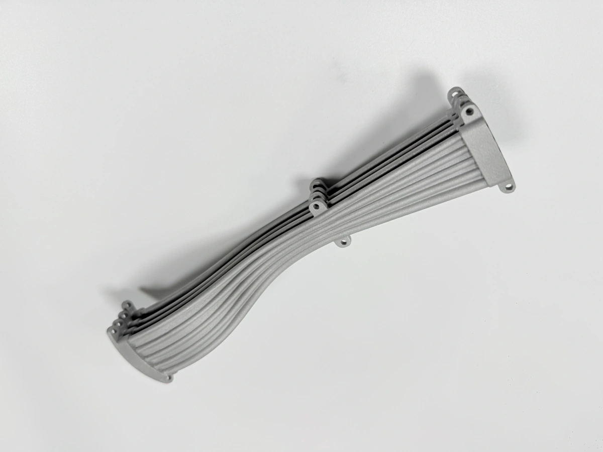
Engineers should design internal channels in 3D printed superalloy components with powder removal, build orientation, thermal stress, wall thickness, channel inspection, and post-processing in mind. Internal channels are one of the strongest reasons to use superalloy 3D printing, especially for turbine, combustion, heat exchanger, nozzle, and hot-gas path components. However, poor channel design can cause trapped powder, blocked flow paths, internal defects, rough surfaces, cracking, and inspection difficulty.
For high-temperature superalloy parts, internal channels should not be designed only for fluid flow or cooling performance. They must also be manufacturable by additive manufacturing. Channel diameter, curvature, overhang angle, drain access, wall thickness, surface roughness, and inspection method should be reviewed before quotation and production.
1. Direct Answer: How Should Internal Channels Be Designed?
Internal channels in 3D printed superalloy parts should be designed with smooth transitions, sufficient channel size, powder escape paths, accessible inspection routes, and minimal unsupported internal overhangs. Engineers should avoid fully sealed cavities, extremely narrow passages, sharp internal corners, sudden section changes, and hidden channels that cannot be cleaned or inspected after printing.
For metal Powder Bed Fusion, every internal channel is formed layer by layer inside a powder bed. This means the channel must allow unfused powder to escape after printing. If powder cannot be removed, the part may fail flow testing, thermal testing, or customer inspection even if the external geometry looks correct.
Internal Channel Design Rule | Why It Matters | Recommended Review |
|---|---|---|
Provide powder escape paths | Unfused powder must be removed after printing. | Add drain holes, access ports, or open channel exits where possible. |
Avoid very narrow channels | Small passages can trap powder and increase surface roughness impact. | Review minimum channel size according to material, length, and cleaning method. |
Use smooth channel transitions | Sharp transitions increase stress, flow loss, and cleaning difficulty. | Add radii and avoid abrupt internal corners. |
Minimize unsupported internal overhangs | Internal supports may be impossible to remove after printing. | Use self-supporting channel shapes or adjust build orientation. |
Plan inspection access | Internal channels may hide powder residue, cracks, or porosity. | Confirm whether X-ray, CT, borescope, or flow testing is needed. |
2. Which Internal Channel Shapes Are Better for Superalloy 3D Printing?
Channel shape has a major effect on printability. Circular channels may be ideal for fluid performance, but they can create unsupported upper surfaces depending on size and orientation. Teardrop, diamond, oval, and arch-like channels may be easier to print because they reduce unsupported overhangs and improve powder removal.
For superalloys, the channel shape should also consider thermal stress and surface condition. Internal channels in high-temperature parts may experience pressure, flow, oxidation, and thermal cycling, so the design must balance flow performance with manufacturability and inspection feasibility.
Channel Shape | Manufacturing Consideration | Typical Use Direction |
|---|---|---|
Round channel | Good for flow but may need orientation review to avoid unsupported upper surfaces. | Cooling channels, pressure passages, fluid paths. |
Teardrop channel | Often more self-supporting in vertical or inclined builds. | Cooling passages and powder-removal-friendly internal channels. |
Diamond channel | Can reduce unsupported horizontal surfaces but may affect flow behavior. | Structural lightweighting and internal lattice-like flow features. |
Oval channel | May improve packaging but needs review for roof angle and powder removal. | Thin-wall components, compact ducts, thermal management parts. |
Sharp rectangular channel | Higher risk of stress concentration, poor surface quality, and unsupported corners. | Should be avoided or modified with fillets where possible. |
3. How Should Engineers Plan Powder Removal?
Powder removal is one of the most important design issues for internal channels. In powder bed fusion, the part is surrounded and filled with loose powder during printing. After printing, this powder must be removed through channel openings, drain holes, vibration, air flow, ultrasonic cleaning, or other cleaning methods.
Complex channel networks, blind holes, small passages, long curved channels, and dead-end cavities are high-risk features. If powder remains trapped, it can block flow, contaminate later testing, affect weight, or create problems during heat treatment and service.
Powder Removal Issue | Risk | Design Recommendation |
|---|---|---|
Dead-end channel | Powder may remain trapped with no exit path. | Add an outlet, drain hole, or removable access feature. |
Long curved channel | Powder may bridge or remain in bends. | Use larger radii, avoid sharp bends, and confirm cleaning method. |
Small cross-section passage | High risk of blockage and roughness-related flow loss. | Increase channel size or separate prototype testing from final design. |
Complex channel network | Difficult to confirm full powder removal visually. | Plan inspection by CT, X-ray, borescope, flow test, or weight comparison. |
Fully sealed cavity | Powder cannot be removed after printing. | Avoid sealed cavities unless powder retention is intentional and accepted. |
4. How Do Internal Channels Affect Thermal Stress and Cracking?
Internal channels change local wall thickness, heat flow, and stiffness. In superalloy components, these changes can increase thermal stress during printing and later heat treatment. Thin walls around channels may cool faster than surrounding heavy sections, creating stress concentration and distortion risk.
This is especially important for turbine, nozzle, combustion, and hot-gas path components. For example, Inconel 718 3D printed parts for aerospace, turbine, and energy applications, Why choose Haynes 188 for 3D printed combustion and hot-gas path components, and Can Inconel 713C be 3D printed for turbine vanes, nozzles, and hot-section prototypes all involve applications where internal geometry, heat exposure, and alloy behavior must be reviewed together.
Channel-Related Stress Feature | Possible Risk | Control Method |
|---|---|---|
Thin wall around channel | Cracking, local deformation, or heat treatment distortion. | Review minimum wall thickness and add gradual transitions. |
Channel near heavy boss | Uneven cooling and residual stress concentration. | Smooth the mass transition and adjust orientation. |
Sharp internal channel corner | Stress concentration during printing and thermal cycling. | Add internal radii and avoid square corners. |
Dense channel cluster | Local heat accumulation, distortion, and inspection difficulty. | Review channel spacing, build direction, and CT inspection feasibility. |
5. How Should Internal Channels Be Inspected?
Internal channels are difficult to inspect because many defects are hidden from external view. For functional parts, inspection should be planned before printing. The selected inspection method depends on channel size, wall thickness, material density, geometry complexity, and customer acceptance requirements.
X-Ray Inspection can help screen selected internal defects in additive manufacturing parts. For more complex internal channels, CT inspection may be needed to evaluate powder residue, blockage, internal cracks, porosity, and channel shape. External geometry can also be verified through 3D Scanning (FAI): Full-Surface CAD Deviation Control for AM, especially when freeform surfaces and channel-related outer walls must match CAD.
Inspection Method | What It Can Verify | Best Use Case |
|---|---|---|
Visual inspection | Openings, visible powder, obvious blockage, surface damage. | Simple open channels and external access points. |
Borescope inspection | Internal surface condition and partial powder residue. | Larger channels with direct access. |
Flow testing | Basic channel continuity and blockage risk. | Cooling passages, nozzles, ducts, and fluid channels. |
X-ray inspection | Selected internal defects, voids, and simplified internal structures. | High-value parts with inspectable geometry. |
CT inspection | Channel shape, powder residue, porosity, cracks, blockage, and internal geometry deviation. | Complex cooling channels, enclosed passages, and critical hot-section parts. |
3D scanning | External surface deviation and channel-related outer wall deformation. | Freeform turbine, nozzle, duct, and hot-gas path components. |
6. When Should DED Be Considered Instead of Powder Bed Fusion?
Powder bed fusion is usually preferred for precise internal channels, thin walls, and detailed superalloy components. However, Directed Energy Deposition may be considered for large superalloy structures, repair work, feature addition, or local material buildup where fine enclosed channels are not the main requirement.
DED is generally not the first choice for small, enclosed, high-resolution internal channels. Instead, it is more relevant when the project involves large-format superalloy deposition, worn part repair, surface enhancement, or adding material to an existing component. Case references such as LMD 3D Printing Service: Precision Superalloy Deposition for Repairs & Enhancements can help customers understand when deposition-based superalloy manufacturing is more suitable than fine-channel PBF printing.
Process | Better For | Internal Channel Limitation |
|---|---|---|
Powder Bed Fusion | Precise internal channels, complex hot-section parts, thin walls, detailed geometry. | Requires powder removal and careful support-free internal design. |
Directed Energy Deposition | Large parts, repair, feature buildup, local reinforcement, surface enhancement. | Less suitable for fine enclosed channels and high-resolution internal passages. |
7. What Case Experience Supports Complex Superalloy Channel Design?
Complex internal channels are often used in aerospace, aviation, turbine, combustion, and industrial superalloy components. Customers should evaluate whether the supplier has experience with high-precision superalloy printing, post-processing, and inspection rather than only checking whether the material is available.
Case references such as DMLS 3D Printing Service: High-Precision Superalloy Parts for Aerospace and Aviation Industry are useful when reviewing internal channels, thin-wall geometry, heat-resistant materials, and high-precision superalloy applications. They help connect channel design with real manufacturing controls such as build orientation, finishing, inspection, and dimensional validation.
Supplier Capability | Why It Matters for Internal Channels |
|---|---|
Superalloy printability review | Confirms whether the selected alloy and channel geometry are suitable for printing. |
Build orientation planning | Reduces internal overhangs, trapped powder, distortion, and support-removal risk. |
Powder removal strategy | Prevents blocked channels, flow failure, and powder contamination during testing. |
Post-processing capability | Supports stress relief, heat treatment, HIP evaluation, CNC machining, EDM, and surface finishing. |
Inspection support | Helps verify internal channel quality, external deviation, surface defects, and dimensional accuracy. |
8. What RFQ Data Is Needed for Internal Channel Review?
To evaluate internal channels in 3D printed superalloy components, customers should provide complete geometry, application, and inspection data. This helps determine whether the channel can be printed, cleaned, inspected, and used safely in the intended environment.
RFQ Data | Why It Is Needed |
|---|---|
3D CAD file | Used to evaluate channel size, curvature, build orientation, support risk, and powder removal. |
2D drawing | Defines critical dimensions, tolerances, wall thickness, datums, and inspection requirements. |
Channel purpose | Clarifies whether the channel is for cooling, fluid flow, weight reduction, pressure, or gas distribution. |
Minimum channel size | Important for powder removal, flow performance, roughness impact, and inspection feasibility. |
Wall thickness around channels | Helps assess cracking, distortion, thermal stress, and machining allowance. |
Operating temperature | Helps evaluate alloy suitability, thermal cycling risk, and post-processing needs. |
Pressure or flow requirement | Determines whether leakage, blockage, internal surface quality, or flow testing must be controlled. |
Inspection standard | Defines whether visual inspection, borescope, flow testing, X-ray, CT, 3D scanning, or FAI is needed. |
9. Summary
Engineers should design internal channels in 3D printed superalloy components by considering powder removal, channel shape, minimum channel size, wall thickness, thermal stress, inspection access, and post-processing from the beginning of the project. Smooth transitions, sufficient openings, self-supporting channel geometry, and accessible cleaning paths are critical for manufacturable internal passages.
For turbine, combustion, heat exchanger, nozzle, and hot-gas path applications, customers should provide CAD files, drawings, channel purpose, channel size, wall thickness, operating temperature, pressure or flow requirements, post-processing needs, and inspection standards. This allows the supplier to evaluate whether powder bed fusion, directed energy deposition, or another manufacturing route is most suitable for the superalloy component.