Can Inconel 713C Be 3D Printed for Turbine Vanes, Nozzles, and Hot-Section Prototypes?
Inconel 713C, also known in some Chinese alloy systems as GH4099-class nickel-based superalloy, is widely associated with turbine vanes, nozzle guide components, gas-path hardware, turbocharger hot-section parts, and high-temperature prototype components. For engineers developing turbine systems, combustion hardware, or small-batch thermal test parts, one common question is whether Inconel 713C 3D printing is a practical manufacturing route.
The direct answer is: Inconel 713C / GH4099-class alloys can be considered for 3D printing evaluation in selected turbine and hot-section applications, but they should not be treated as standard easy-to-print nickel alloys. Compared with more commonly printed materials such as Inconel 625 or Inconel 718, 713C-class alloys require more careful control of cracking risk, residual stress, thermal distortion, support design, heat treatment, and post-machining strategy.
For this reason, an Inconel 713C turbine part should be evaluated as an engineering manufacturing project, not only as a simple printing order. The best results usually come from combining additive manufacturing with design-for-printing review, controlled thermal processing, CNC machining, EDM, and inspection.
Why Turbine Applications Use 713C-Class Alloys
Inconel 713C is a precipitation-strengthened nickel-based superalloy designed for high-temperature service. It is valued for high-temperature strength, oxidation resistance, and creep resistance, which makes it suitable for components exposed to hot gas flow, thermal cycling, vibration, and mechanical load.
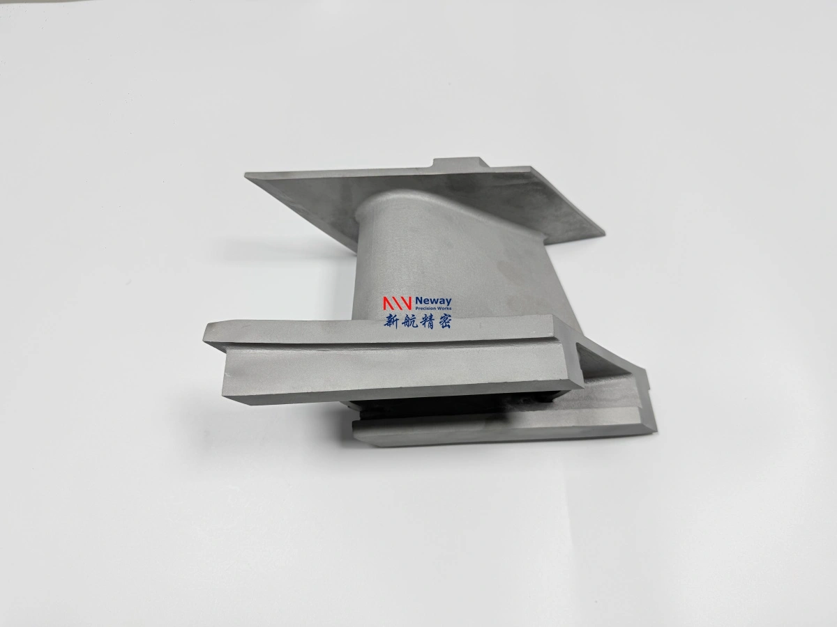
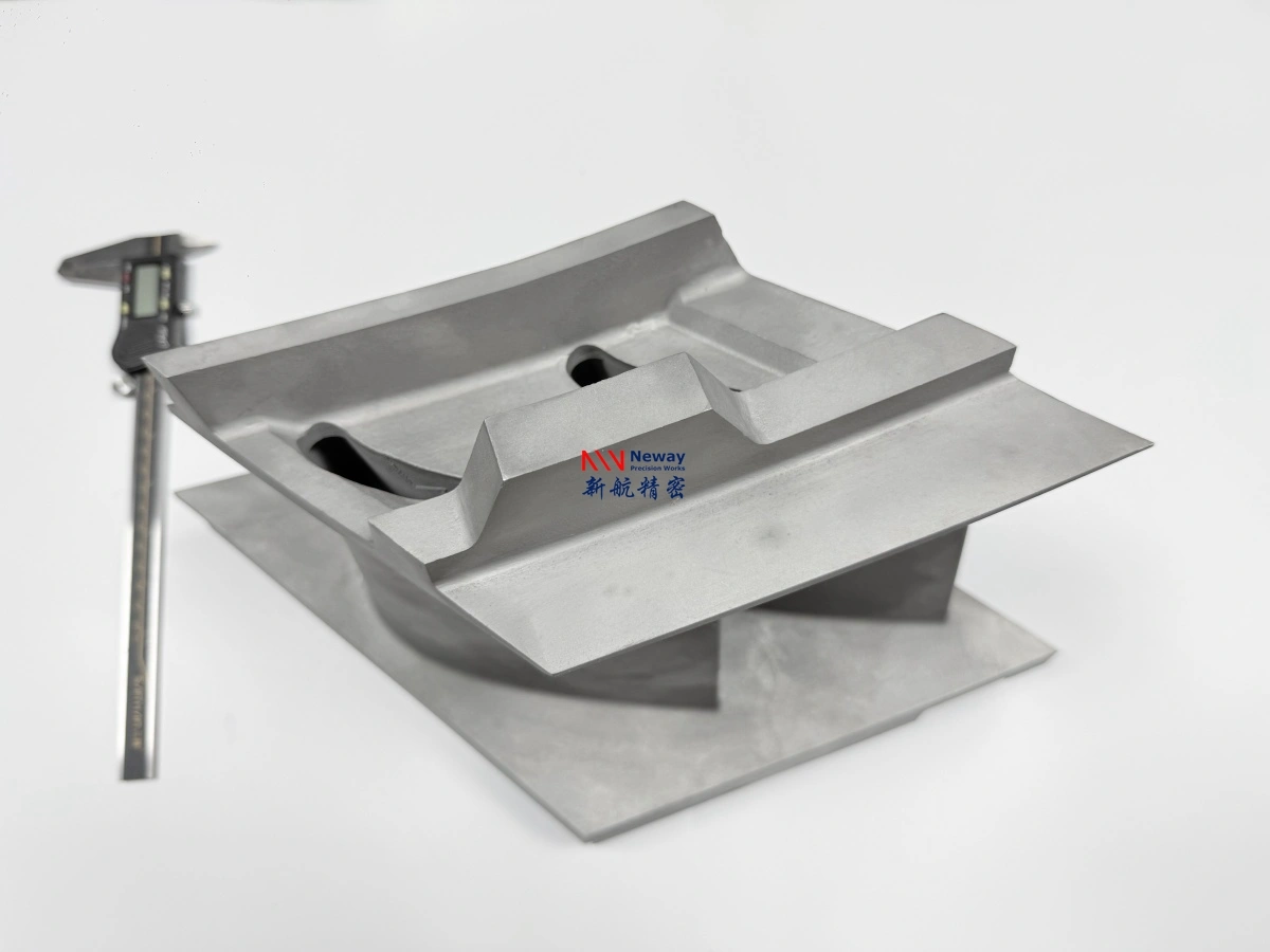
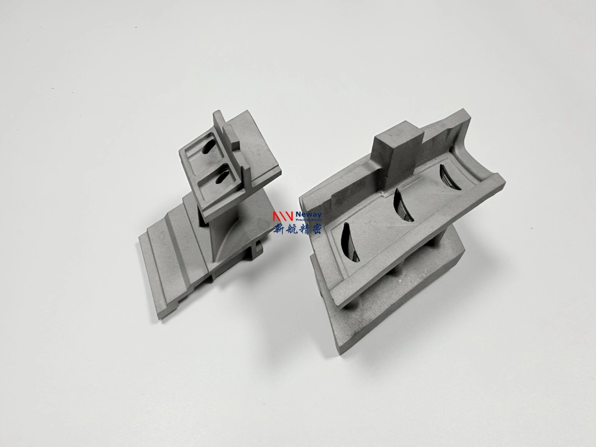
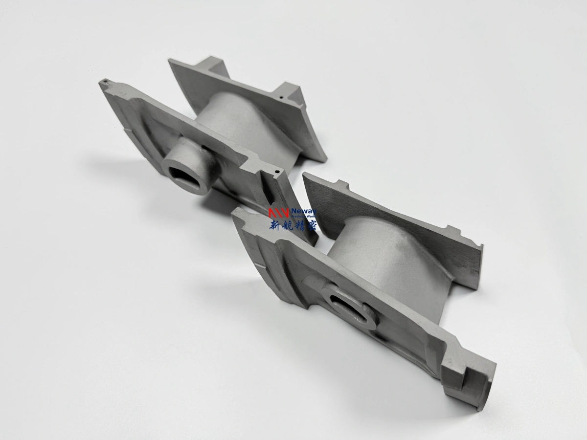
These properties explain why 713C-class materials are often used or considered for turbine vanes, nozzle guide vanes, small turbine blades, gas-path structures, turbocharger hot-section parts, high-temperature brackets, and thermal test components.
In traditional manufacturing, many of these parts are produced by investment casting and then finished by CNC machining, EDM, coating, and inspection. However, when the design is still under development, casting tooling can be expensive and slow. This is where superalloy 3D printing may add value for small-batch validation and prototype development.
What Inconel 713C Parts Can Be Considered for 3D Printing?
Inconel 713C 3D printing is most suitable when the project goal is prototype validation, geometry testing, flow-path evaluation, assembly checking, or low-volume hot-section development. It is especially useful when the part has complex geometry or when the customer wants to avoid investment casting tooling before the design is finalized.
Part Type | 3D Printing Suitability | Key Engineering Concern |
|---|---|---|
Turbine vanes | Possible for prototype evaluation | Thin-wall control, airfoil distortion, datum alignment |
Nozzle guide components | Suitable for small-batch validation | Flow-path accuracy, internal cleaning, post-machining allowance |
Turbine blade prototypes | Possible for non-qualified prototype testing | Fatigue, creep, balance, and qualification requirements |
Hot-section brackets | Generally feasible after review | Residual stress, thermal load, mounting surface machining |
Gas-path test pieces | Good candidate for R&D iteration | Wall thickness, oxidation, surface condition, inspection |
High-temperature fixtures | Suitable for custom small batches | Load condition, thermal cycling, machining tolerance |
For final rotating turbine blades or safety-critical engine hardware, 3D printing requires strict process qualification, material testing, and application-specific validation. For early prototypes, test rigs, and development components, it can be a practical way to evaluate geometry before committing to a production route.
Where 3D Printing Adds Value for Inconel 713C Hot-Section Prototypes
The main value of 3D printing is not simply replacing casting. For Inconel 713C hot-section components, additive manufacturing is most useful when engineers need to validate a design quickly before investing in tooling or production fixtures.
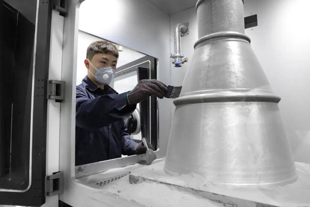
Using powder bed fusion, complex turbine-related geometries can be manufactured directly from CAD data. This allows engineers to evaluate assembly fit, cooling passage layout, gas-flow structure, support strategy, machining datum, and critical interface design earlier in the development cycle.
For small batches, 3D printing can also reduce upfront tooling cost. This is especially valuable for aerospace, energy, turbine R&D, turbocharger, and thermal testing customers who may need only one to ten parts before deciding whether to continue with additive manufacturing, CNC/EDM, or investment casting.
Key Manufacturing Risks of 3D Printing Inconel 713C
Inconel 713C is not as easy to print as some standard additive nickel alloys. Its alloy chemistry and strengthening mechanism can increase sensitivity to hot cracking, residual stress, and thermal distortion during laser melting and cooling. Before quotation and production, the part geometry should be reviewed carefully.
1. Cracking Sensitivity
713C-class superalloys may be sensitive to cracking during printing, especially around sharp transitions, thick-to-thin section changes, unsupported features, and high thermal gradient areas. A successful print normally requires careful orientation, support design, laser parameter control, and post-print stress management.
2. Thin-Wall and Airfoil Deformation
Turbine vanes, nozzles, and gas-path components often include thin walls or airfoil-like profiles. These features may deform during printing, stress relief, support removal, or machining. Proper allowance, fixture planning, and inspection datum control are important for final dimensional accuracy.
3. Support Removal and Powder Cleaning
Internal passages, narrow slots, blind cavities, and enclosed gas-flow structures may trap powder or make support removal difficult. If powder cannot be fully removed, the part may not be suitable for thermal testing or functional flow-path validation. Internal geometry should be checked before confirming printability.
4. Post-Processing and Machining Requirements
Most 3D printed turbine components cannot be used directly after printing. Mounting faces, sealing surfaces, holes, slots, datum areas, and assembly interfaces usually require CNC machining or EDM. For this reason, the 3D model and drawing should include sufficient machining allowance on critical features.
Recommended Workflow for Inconel 713C 3D Printed Turbine Parts
For Inconel 713C hot-section components, a reliable workflow should combine additive manufacturing with post-processing and inspection. The exact route depends on part geometry, quantity, temperature exposure, and quality requirements, but a typical process may include:
Design for additive manufacturing and printability review
Build orientation, support design, and powder removal assessment
Powder bed fusion printing
Stress relief or controlled heat treatment
Optional hot isostatic pressing evaluation for density improvement
CNC machining or EDM for critical surfaces, holes, slots, and datum features
Dimensional inspection and non-destructive testing
This workflow is especially important for turbine rigs, nozzle prototypes, combustion test parts, high-temperature brackets, and energy equipment development, where part geometry, material integrity, and high-temperature performance all affect the final result.
Applications in Aerospace, Energy, and Turbine Development
Inconel 713C 3D printed prototypes are often considered in early-stage turbine and propulsion development. In aerospace and aviation projects, engineers may use printed prototypes to validate vane geometry, nozzle structure, mounting interfaces, airfoil profiles, or hot gas path features before investing in casting tooling.
For energy and power applications, 3D printed 713C-class parts may be used for gas turbine test rigs, burner development, thermal cycling fixtures, turbocharger hot-section prototypes, or small-batch replacement development. These projects often require close coordination between material selection, operating temperature, thermal cycling, load condition, and inspection requirements.
When Should You Consider Casting Instead of 3D Printing?
Although 3D printing is useful for prototype validation, it is not always the best route for Inconel 713C parts. If the component is already production-qualified as an investment casting, if the geometry is suitable for casting, or if high-volume repeatability is the main priority, investment casting may still be more suitable.
For final production turbine hardware, the correct manufacturing route depends on mechanical property requirements, certification level, surface quality, dimensional tolerance, inspection standard, and cost target. In many development programs, the practical route is to use 3D printing for prototype validation first, then move to casting or another production process after the design is stable.
RFQ Checklist for Inconel 713C 3D Printed Parts
To evaluate whether your Inconel 713C or GH4099 hot-section part can be printed, please provide enough engineering information for manufacturability review. This helps determine whether the part is suitable for printing, whether CNC/EDM finishing is required, and whether heat treatment or HIP should be considered.
Recommended RFQ information includes:
3D CAD file in STEP, X_T, or STL format
2D drawing with tolerances, datum references, and critical dimensions
Required material grade, such as Inconel 713C, GH4099, or acceptable equivalent alloy
Prototype quantity and possible future batch quantity
Minimum wall thickness, airfoil details, and internal channel geometry
Operating temperature, thermal cycling, vibration, and load conditions
Required post-processing, including heat treatment, HIP, CNC machining, EDM, coating, or polishing
Inspection requirements such as CMM, CT scanning, X-ray, FPI, FAI, or material testing
FAQ
Is Inconel 713C 3D Printing Suitable for Turbine Vane and Nozzle Prototypes?
Should Turbine Developers Choose Inconel 713C 3D Printing or Investment Casting?
What Post-Processing Controls Are Needed for Inconel 713C 3D Printed Parts?
What Technical Data Is Required to Quote Inconel 713C Turbine or Hot-Section Parts?