Is Inconel 713C 3D Printing Suitable for Turbine Vane and Nozzle Prototypes?
Is Inconel 713C 3D Printing Suitable for Turbine Vane and Nozzle Prototypes?
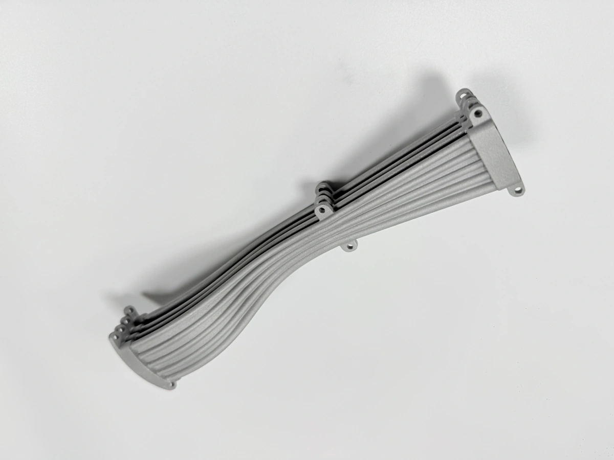
Inconel 713C 3D printing can be evaluated for turbine vane, turbine nozzle, and hot-section prototype development, especially when customers need small-batch validation before tooling, casting, or final production. Because turbine vanes and nozzles often include thin walls, curved gas-path surfaces, cooling-related structures, and high-temperature service requirements, the project must be reviewed carefully before production.
For turbine development projects, Inconel 713C turbine parts are usually not treated as standard printed components. They require a feasibility review covering material behavior, geometry, wall thickness, support removal, powder removal, heat treatment, machining allowance, and inspection requirements.
1. Direct Answer: Is Inconel 713C Suitable for Turbine Vane and Nozzle Prototypes?
Inconel 713C may be suitable for turbine vane and nozzle prototypes when the goal is geometry validation, assembly checking, aerodynamic concept testing, hot-section prototype evaluation, or small-batch engineering verification. However, suitability depends strongly on the part geometry, wall thickness, thermal exposure, mechanical load, and required inspection level.
For prototype projects, the main advantage of Inconel 713C 3D printing is that customers can evaluate complex turbine or nozzle geometry without immediately investing in casting tooling. This is especially useful when the design may still change after flow testing, installation review, or thermal validation.
Application Question | Practical Answer |
|---|---|
Can Inconel 713C be used for turbine vane prototypes? | Yes, it can be evaluated for prototype vanes, but thin-wall geometry and cracking risk must be reviewed first. |
Can it be used for turbine nozzle prototypes? | Yes, especially for small-batch nozzle or nozzle ring validation before final production planning. |
Is it suitable for final production parts? | It depends on the application, testing standard, inspection requirements, and customer acceptance criteria. |
What is the main project risk? | Cracking, thin-wall distortion, support removal, powder removal, and post-machining control. |
2. Which Turbine and Hot-Section Parts Can Be Evaluated?
Inconel 713C is often considered for high-temperature gas-path and turbine-related components. For 3D printing projects, it is most suitable when the part is needed for prototype testing, design iteration, assembly verification, or limited-volume engineering validation.
Part Type | Typical Prototype Purpose |
|---|---|
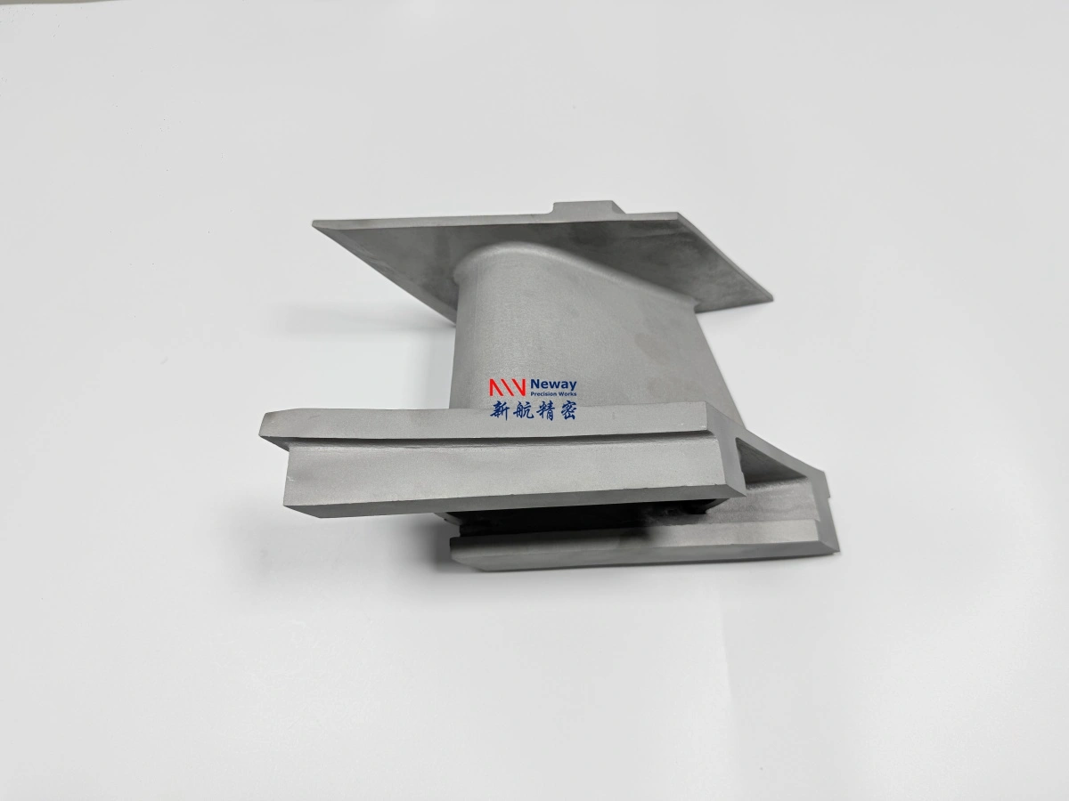
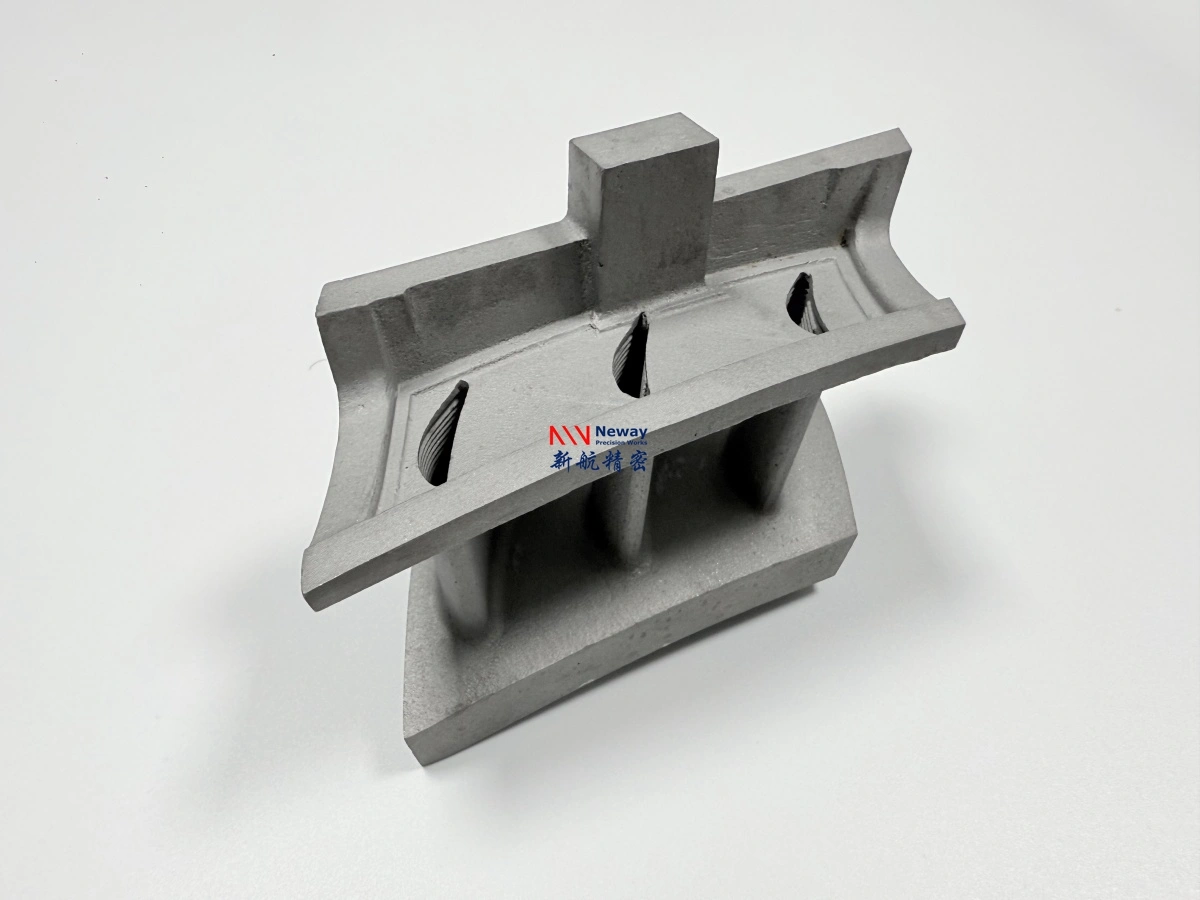
Turbine vanes | Used to validate gas-path shape, mounting interfaces, wall thickness, and assembly fit. |
Turbine nozzles | Used to evaluate flow direction, nozzle geometry, thermal exposure, and installation features. |
Nozzle rings | Used for small-batch testing before casting or production process confirmation. |
Hot-section brackets | Used for high-temperature structural support and fixture validation. |
Gas-path components | Used to test airflow surfaces, mounting features, and thermal behavior. |
Combustion or test-rig fixtures | Used for laboratory, engine test, or thermal cycling validation. |
These projects are commonly linked to aerospace and aviation development, as well as energy and power equipment validation, where high-temperature prototypes are needed before full production investment.
3. Why Does 3D Printing Help Turbine Vane and Nozzle Development?
3D printing helps turbine vane and nozzle development because it allows engineers to evaluate complex geometry faster than conventional tooling-based processes. For prototype work, this can reduce design iteration time and help identify geometry, assembly, and functional risks before committing to casting tooling or long-cycle production methods.
With powder bed fusion, turbine-related prototypes can be built directly from CAD data. This is useful for parts with curved profiles, integrated mounting features, internal passages, thin-wall sections, or complex gas-path shapes.
Development Need | How 3D Printing Helps |
|---|---|
Aerodynamic shape validation | Allows quick testing of vane, nozzle, and gas-path geometry before final design freeze. |
Cooling or flow feature evaluation | Supports complex channels or flow-related structures that may be difficult to machine directly. |
Assembly interface checking | Helps verify mounting holes, flanges, datum faces, and installation clearances. |
Small-batch prototype testing | Enables low-volume validation without immediate investment in casting molds or tooling. |
Design iteration | Allows engineers to modify geometry after test feedback and print updated versions. |
4. Key Manufacturing Risks for Printed Inconel 713C Turbine Parts
Turbine vanes and nozzles are challenging because they often combine thin walls, curved surfaces, sharp transitions, internal channels, high-temperature service, and tight interface requirements. These features increase the difficulty of Inconel 713C 3D printing.
Manufacturing Risk | Impact on Turbine or Nozzle Prototypes |
|---|---|
Thin-wall distortion | Vane airfoils and nozzle walls may deform during printing, stress relief, or support removal. |
Cracking | Inconel 713C is crack-sensitive, especially around stress concentration areas and rapid thickness changes. |
Support removal difficulty | Supports inside narrow passages, curved gas-path areas, or hidden surfaces may be difficult to remove. |
Powder removal | Closed cavities or fine channels may trap powder and require special cleaning or CT confirmation. |
Surface roughness | As-printed surfaces may not be acceptable for aerodynamic or sealing areas without finishing. |
Post-machining allowance | Mounting faces, sealing surfaces, holes, and datum features often need CNC machining or EDM after printing. |
Inspection complexity | Internal defects, cracks, and powder residue may require CT, X-ray, FPI, CMM, or 3D scanning. |
5. What Design Details Should Be Reviewed Before Printing?
Before producing an Inconel 713C turbine vane or nozzle prototype, the CAD model should be reviewed for printability, support accessibility, heat accumulation, powder removal, and final machining requirements. A design that is suitable for casting or CNC machining may still require adjustment for additive manufacturing.
Design Detail | Review Focus |
|---|---|
Minimum wall thickness | Checks whether vane or nozzle walls can survive printing, support removal, and heat treatment. |
Leading and trailing edges | Reviews risk of overheating, deformation, insufficient material, or finishing difficulty. |
Internal channels | Checks whether powder can be removed and whether internal surfaces can be inspected. |
Mounting interfaces | Identifies surfaces that need machining allowance, flatness control, or datum definition. |
Sharp transitions | Reduces cracking and stress concentration by adding fillets or smoother geometry where possible. |
Inspection access | Confirms whether defects, powder residue, or blocked channels can be detected after printing. |
6. What Information Is Needed for a Turbine Vane or Nozzle RFQ?
To quote Inconel 713C turbine vane or nozzle prototypes accurately, customers should provide both geometry data and service-condition information. This helps determine whether the project is suitable for printing, what post-processing is needed, and which inspection method should be included.
Required Information | Why It Is Needed |
|---|---|
3D CAD file | Used to evaluate geometry, build orientation, support design, and powder removal feasibility. |
2D drawing | Defines tolerances, datums, critical dimensions, holes, threads, and machining surfaces. |
Minimum wall thickness | Important for vane airfoils, nozzle walls, thin edges, and crack-risk review. |
Operating temperature | Helps evaluate whether Inconel 713C and the selected post-processing route are suitable. |
Thermal cycling condition | Important for hot-section prototypes exposed to repeated heating and cooling. |
Load and pressure condition | Helps assess whether additional inspection, HIP, or mechanical testing should be considered. |
Quantity | Affects build layout, process validation scope, unit price, and lead time. |
Inspection requirements | Defines whether CT, X-ray, FPI, CMM, 3D scanning, material certificate, or FAI is required. |
7. Summary
Inconel 713C 3D printing may be suitable for turbine vane, turbine nozzle, nozzle ring, and hot-section prototype development, especially when the customer needs small-batch validation before casting, tooling, or production design freeze. It can help engineers evaluate aerodynamic geometry, cooling-related structures, assembly interfaces, and high-temperature prototype concepts more quickly.
However, Inconel 713C turbine parts require careful feasibility review because of crack sensitivity, thin-wall distortion, support removal difficulty, powder removal risk, surface roughness, and post-machining requirements. For an accurate quotation, customers should provide the 3D model, 2D drawing, wall thickness, application temperature, thermal cycling condition, load information, quantity, and inspection standard.