Managing Cracking, Distortion, and Thin Walls in Inconel 713C 3D Printed Superalloy Parts
Inconel 713C / GH4099-class nickel-based superalloys are attractive for turbine vanes, nozzle guide parts, hot-section brackets, gas-path prototypes, and high-temperature test components. However, compared with more commonly printed alloys such as Inconel 718, Inconel 713C 3D printed parts require much more careful process control.
The main challenge is not only high-temperature performance. For additive manufacturing, the more important concerns are cracking sensitivity, residual stress, thermal distortion, thin-wall deformation, support removal, powder cleaning, post-machining allowance, and inspection planning. If these issues are not reviewed before printing, the part may fail during manufacturing or require excessive rework after printing.
For turbine vanes, nozzles, and thin-wall hot-section components, Inconel 713C 3D printing should therefore be treated as an engineering feasibility project. A successful result depends on the combination of DfAM review, build orientation, support strategy, heat treatment, optional HIP evaluation, CNC/EDM finishing, and non-destructive inspection.
Why Inconel 713C Needs Process Control
Inconel 713C is a precipitation-strengthened nickel-based superalloy developed for high-temperature applications. Its alloy system provides strength, oxidation resistance, and creep resistance, but it also makes the material more sensitive to thermal stress during laser-based additive manufacturing.
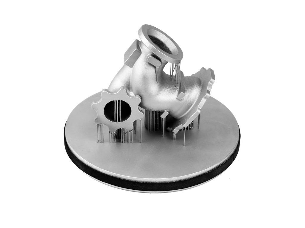
During powder bed fusion 3D printing, the material experiences rapid melting, solidification, and repeated thermal cycling. For 713C-class alloys, this can increase the risk of hot cracking, residual stress accumulation, and distortion, especially in thin-wall structures or complex turbine geometries.
This is why Inconel 713C cannot be handled like a standard printable alloy. The design, build direction, support structure, heat flow, machining allowance, and inspection plan should all be reviewed before production.
Design Factors That Increase Cracking and Distortion Risk
Many cracking and distortion problems are related to part geometry. Even if the alloy powder and printing parameters are suitable, certain design features can create high thermal stress, poor heat dissipation, or difficult support removal.
Common risk factors include:
Very thin walls without enough structural support
Sharp internal corners or sudden section changes
Thick bosses connected directly to thin airfoil sections
Long unsupported edges or overhangs
Closed cavities that trap powder
Internal channels without cleaning access
Critical surfaces located in heavy support-removal areas
Features that require tight tolerance directly after printing
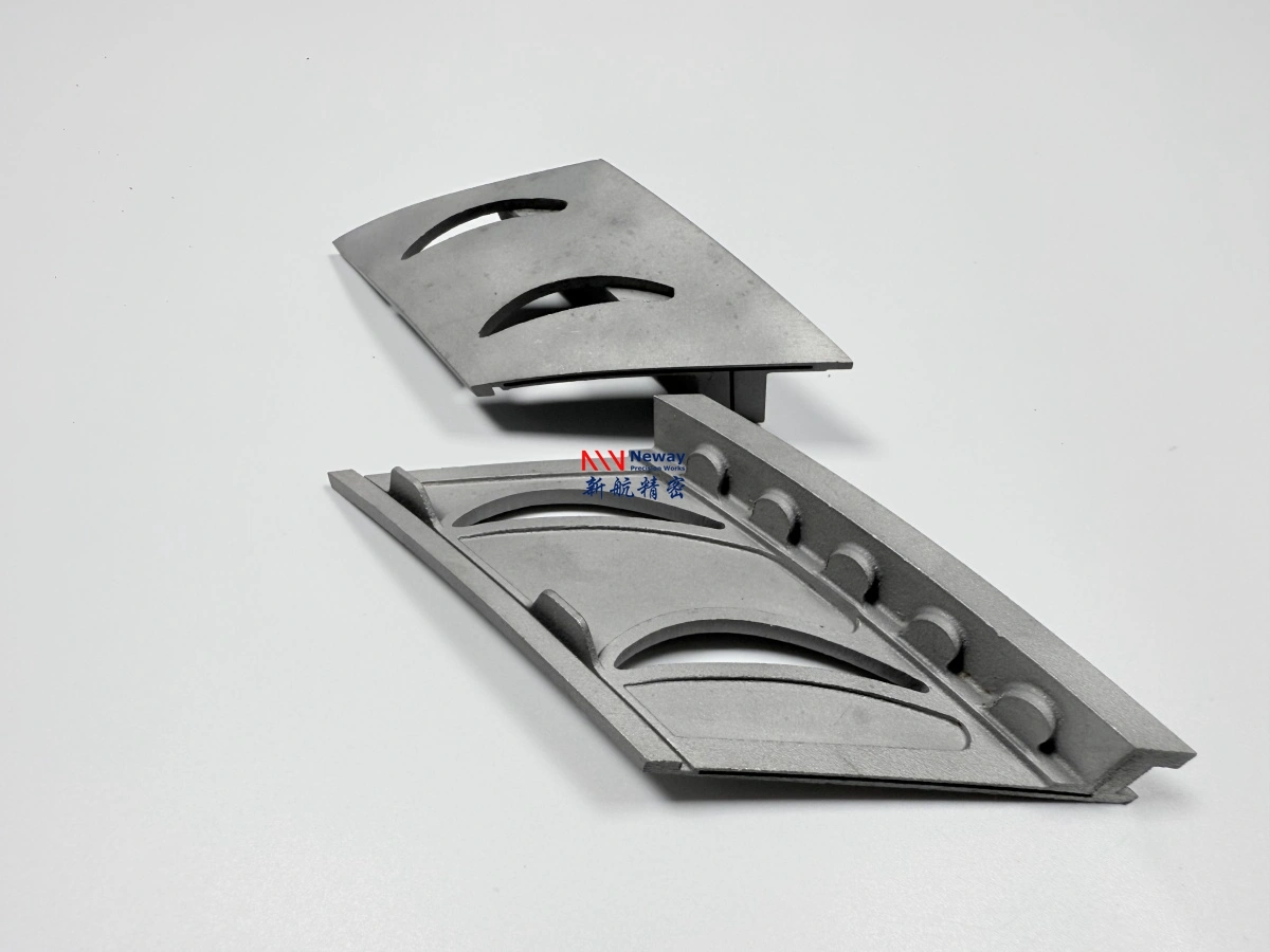
For turbine vanes and nozzle prototypes, the highest-risk areas are usually airfoil edges, thin trailing edges, mounting roots, internal passages, flanges, sealing surfaces, and transitions between heavy and thin sections. These areas should be reviewed during the DfAM stage before confirming the manufacturing route.
Design Feature | Manufacturing Risk | Recommended Review |
|---|---|---|
Thin airfoil wall | Distortion, cracking, edge deformation | Check wall thickness, orientation, and support strategy |
Sharp corner | Stress concentration and crack initiation | Add radius where functionally acceptable |
Thick-to-thin transition | Uneven cooling and residual stress | Review transition geometry and heat flow |
Closed internal cavity | Trapped powder and inspection difficulty | Add powder removal holes or redesign access |
Tight-tolerance hole or slot | As-printed accuracy may be insufficient | Reserve CNC or EDM finishing allowance |
Support Design and Build Orientation
Support design is one of the most important factors for Inconel 713C distortion control. Supports are not only used to hold overhangs. They also help conduct heat, control deformation, and stabilize thin features during printing.
For turbine vanes, nozzle components, and hot-section prototypes, build orientation should be selected according to geometry, thermal stress, support accessibility, machining allowance, and inspection requirements. A build direction that reduces support volume may not always be the best choice if it increases airfoil deformation or places supports on critical gas-flow surfaces.
Good support and orientation planning should consider:
How heat will flow through the part during printing
Whether thin-wall sections are stable during the build
Whether supports can be removed without damaging critical surfaces
Whether powder can be fully removed from internal passages
Whether machining datum surfaces remain accessible after printing
Whether the final inspection method can reach key features
For many Inconel 713C turbine parts, the best orientation is a compromise between printability, distortion control, post-processing access, and final functional requirements.
Heat Treatment and HIP Strategy
Post-print thermal processing is important for 713C-class superalloy parts. A controlled heat treatment service may be used to reduce residual stress, stabilize the microstructure, and prepare the part for downstream machining or testing.
For some applications, hot isostatic pressing may also be evaluated to reduce internal porosity and improve material integrity. However, HIP should not be treated as a universal solution. The decision depends on the part geometry, application load, temperature exposure, defect tolerance, and inspection requirements.
For prototype turbine vanes, nozzles, and gas-path parts, the heat treatment and HIP strategy should be discussed together with the customer’s test purpose. A visual prototype, assembly prototype, thermal fixture, and functional hot-section test component may require different post-processing levels.
Post-Process | Main Purpose | When to Consider It |
|---|---|---|
Stress relief | Reduce residual stress after printing | Thin walls, complex geometry, machining after printing |
Heat treatment | Improve material stability and performance | Functional hot-section prototypes or test components |
HIP | Reduce internal porosity risk | Parts requiring higher internal integrity or thermal testing |
Post-machining | Achieve tolerance and functional interfaces | Mounting faces, sealing faces, holes, slots, datum surfaces |
CNC and EDM Allowance for Functional Features
Most Inconel 713C 3D printed turbine parts should not rely only on as-printed accuracy for critical features. Mounting surfaces, sealing faces, precision holes, slots, vane roots, flange faces, and datum areas usually need post-machining.
CNC machining is commonly used for flatness, sealing surfaces, mounting interfaces, and precision datum features. electrical discharge machining may be required for difficult superalloy slots, small holes, internal features, and complex profiles that are hard to machine conventionally.
To support these finishing steps, the part should include machining allowance in the 3D model or 2D drawing. Without allowance, it may be difficult to remove support marks, correct distortion, or achieve final tolerance on critical features.
Typical features requiring CNC or EDM finishing include:
Mounting faces and flange faces
Sealing surfaces and gasket contact areas
Vane roots and assembly interfaces
Precision holes, slots, and threaded features
Datum surfaces for inspection and assembly
Critical gas-path interfaces requiring controlled geometry
Inspection Plan for Crack, Distortion, and Internal Defects
Inspection planning is essential for Inconel 713C 3D printed superalloy parts. Because cracking, distortion, powder trapping, and internal defects are key manufacturing risks, inspection should be defined before production rather than added after the part is finished.
Common inspection methods may include visual inspection, dimensional inspection, CMM measurement, 3D scanning, X-ray, CT scanning, FAI reporting, and material certificate review. For turbine vanes and nozzle parts, CT or X-ray inspection may be important when internal channels, enclosed cavities, or thin-wall sections are involved.
Inspection Method | What It Checks | Typical Use Case |
|---|---|---|
Visual inspection | Surface cracks, support marks, obvious defects | Initial quality screening |
CMM inspection | Critical dimensions and datum alignment | Machined interfaces and assembly features |
3D scanning | Overall profile deviation and distortion | Airfoil, vane, and complex curved surfaces |
X-ray inspection | Internal defect indications | Hot-section prototypes and structural parts |
CT scanning | Internal channels, porosity, powder trapping | Cooling passages, nozzle structures, enclosed cavities |
FAI report | First article dimensional confirmation | Prototype validation before repeat production |
For aerospace and aviation 3D printing, inspection requirements should be clearly defined at the RFQ stage. This helps avoid misunderstandings about whether the part is only for fit checking, thermal testing, flow-path validation, or functional qualification.
DfAM Checklist for Inconel 713C 3D Printed Parts
A DfAM review helps reduce cracking, distortion, support-removal issues, and post-machining problems before printing begins. For Inconel 713C / GH4099-class superalloy parts, the following items should be checked before quotation and production:
Minimum wall thickness and thin-wall stability
Sharp corners, internal radii, and stress concentration areas
Thick-to-thin transitions and thermal gradient risk
Build orientation and support accessibility
Powder removal holes for internal cavities or channels
Support contact on critical gas-path or sealing surfaces
Machining allowance for datum, sealing, mounting, and precision features
Heat treatment and HIP requirements based on application
Inspection standard for dimensions, cracks, porosity, and internal passages
When to Ask for Engineering Review Before Quotation
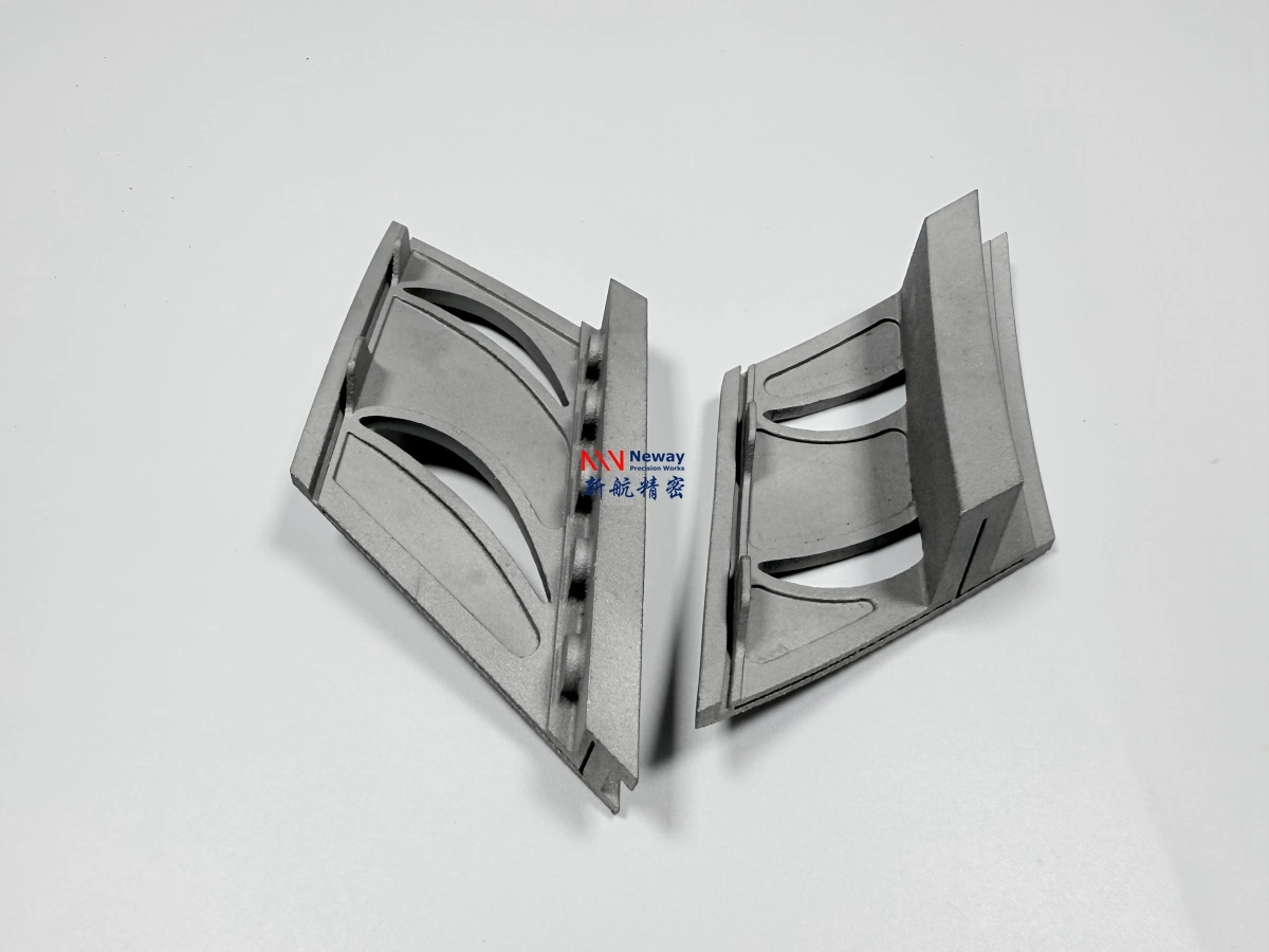
Engineering review is strongly recommended when the part is a turbine vane, nozzle guide component, thin-wall hot-section structure, combustion test part, or high-temperature fixture. These parts often combine thin walls, complex curves, internal passages, thermal exposure, and tight assembly requirements.
A manufacturability review before quotation can help determine whether the part is suitable for printing, whether design changes are needed, where supports should be placed, how much machining allowance is required, and whether heat treatment, HIP, CT scanning, or CMM inspection should be included in the quote.
This review is especially important if the project involves:
Thin-wall turbine vane or nozzle geometry
Internal cooling channels or enclosed cavities
High operating temperature or repeated thermal cycling
Critical mounting, sealing, or datum surfaces
Prototype validation before investment casting
Small-batch turbine components for test rigs or hot-section development
FAQ
Is Inconel 713C 3D Printing Suitable for Turbine Vane and Nozzle Prototypes?
Should Turbine Developers Choose Inconel 713C 3D Printing or Investment Casting?
What Post-Processing Controls Are Needed for Inconel 713C 3D Printed Parts?
What Technical Data Is Required to Quote Inconel 713C Turbine or Hot-Section Parts?