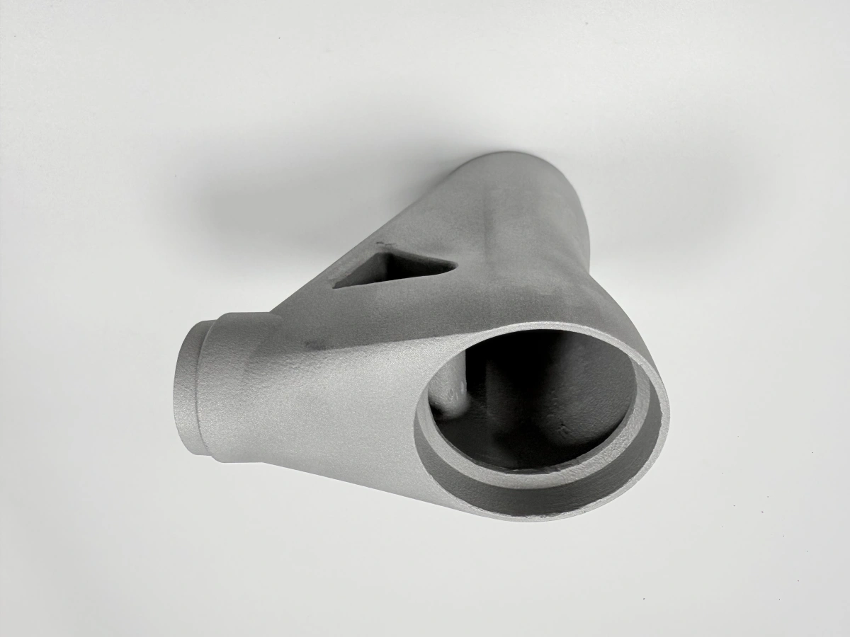
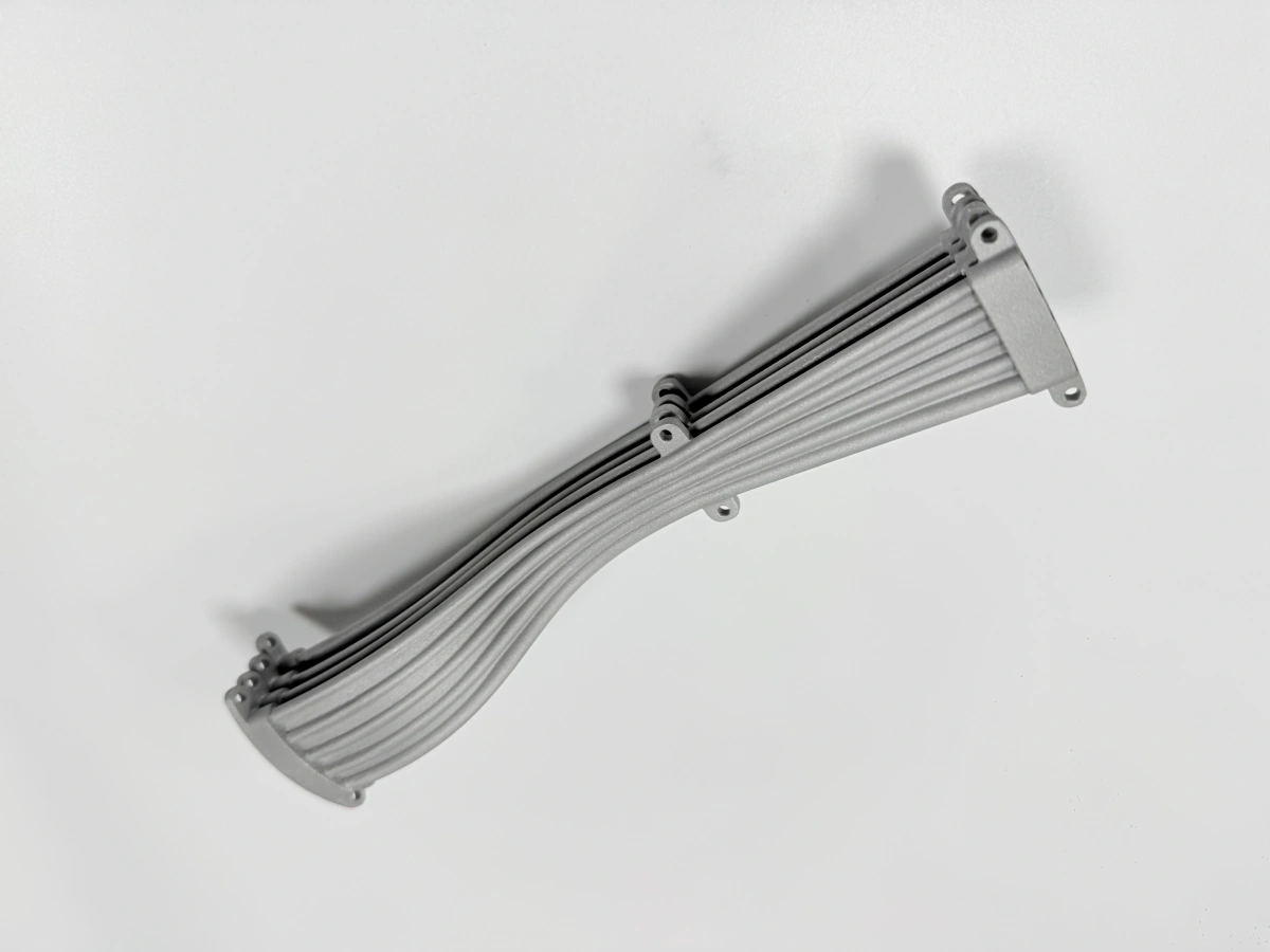
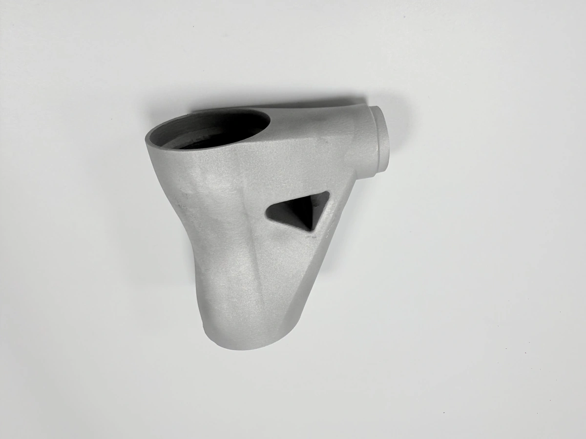
Design Rules for 3D Printed Superalloy Parts with Thin Walls, Cooling Channels, and Complex Geometry
Superalloy 3D printing is widely used for aerospace, turbine, combustion, energy, and high-temperature test components. However, successful parts depend on more than material selection and printing capability. For thin walls, cooling channels, internal cavities, nozzle structures, guide vanes, and complex hot-section geometry, design for additive manufacturing is critical.
A well-prepared design can reduce cracking risk, distortion, support-removal difficulty, powder trapping, post-machining cost, and inspection uncertainty. A poor design may be printable in theory but difficult to clean, machine, inspect, or qualify. For this reason, superalloy 3D printing projects should include DfAM review before quotation and production.
This guide explains practical design rules for 3D printed superalloy parts, especially for thin-wall structures, cooling channels, complex geometries, turbine prototypes, combustion hardware, and high-temperature functional components.
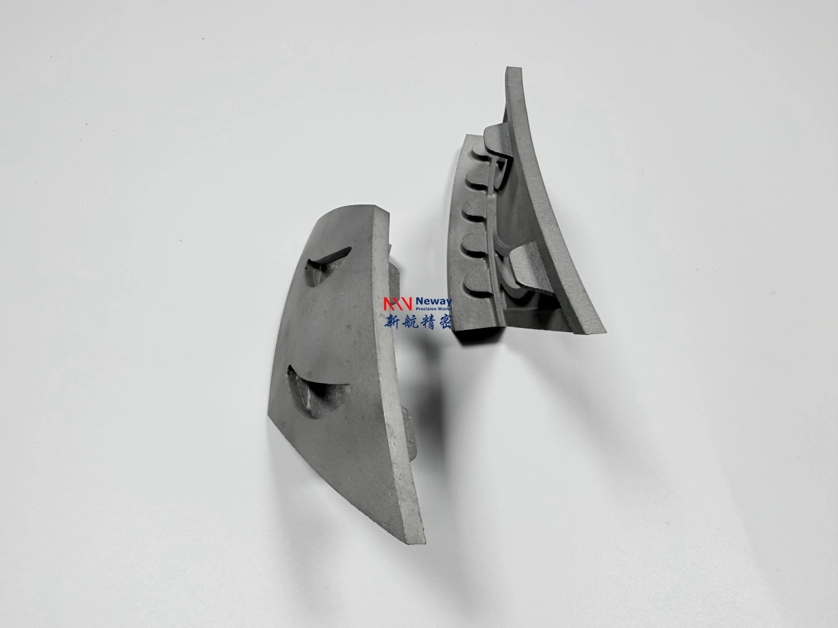
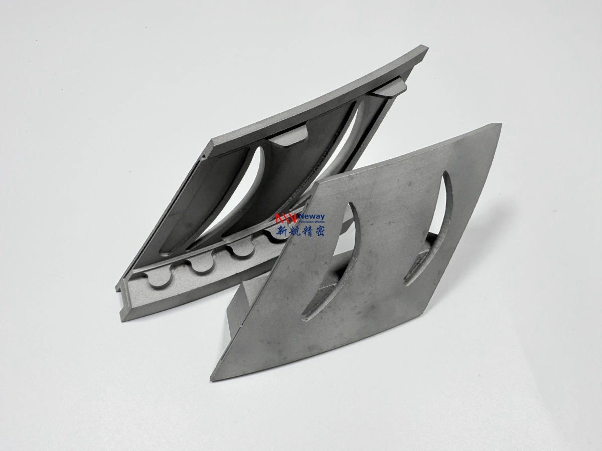
Why DfAM Matters for Superalloy 3D Printing
Superalloys are more demanding than many standard 3D printing materials. Nickel-based and cobalt-based superalloys are often selected for high-temperature strength, oxidation resistance, corrosion resistance, thermal fatigue resistance, or turbine hot-section performance. These same applications usually involve complex geometry, strict inspection, and expensive post-processing.
Design defects can create several manufacturing problems:
Cracking around sharp corners or thick-to-thin transitions
Distortion in thin walls, airfoils, or unsupported sections
Powder trapped inside blind cavities or enclosed channels
Support structures that cannot be removed without damaging the part
Critical surfaces placed in difficult support-removal areas
Insufficient stock for CNC machining or EDM finishing
Internal features that cannot be inspected by CT, X-ray, or borescope
Higher cost caused by unnecessary support volume or excessive post-processing
For aerospace, turbine, and hot-section components, DfAM is not only about making the CAD model printable. It is about making the part printable, cleanable, machinable, inspectable, and suitable for its intended test or operating environment.
Thin-Wall Design for 3D Printed Superalloy Parts
Thin-wall structures are common in turbine vanes, nozzles, combustion parts, heat shields, flow-control parts, and lightweight brackets. They can reduce weight and improve thermal response, but they also increase the risk of distortion, cracking, and dimensional deviation during printing and post-processing.
When designing thin-wall superalloy parts, engineers should review:
Minimum wall thickness based on material, height, and unsupported length
Wall stability during printing, stress relief, and support removal
Rib or local reinforcement options for long unsupported walls
Internal radii to reduce stress concentration
Gradual transitions between thin and thick sections
Machining allowance on sealing faces, flanges, and datum surfaces
Inspection access for thin-wall profile verification
For cobalt-based hot gas path structures, thin-wall design should also consider thermal cycling and oxidation exposure. The Haynes 188 design guide provides more specific guidance for thermally exposed thin-wall components.
Thin-Wall Feature | Possible Risk | Design Recommendation |
|---|---|---|
Long unsupported wall | Warping or vibration during printing | Add ribs, adjust orientation, or review support strategy |
Sharp thin-wall corner | Stress concentration and crack initiation | Add internal radius where functionally acceptable |
Sudden thick-to-thin change | Uneven cooling and residual stress | Use smoother transitions and review heat flow |
Thin airfoil edge | Profile distortion and edge damage | Check build orientation, support contact, and inspection method |
Cooling Channel and Internal Cavity Design
Cooling channels and internal cavities are one of the main reasons engineers choose metal 3D printing for superalloy parts. They can support thermal management, hot gas path testing, weight reduction, and integrated flow-control structures. However, they also create powder removal, support access, surface finish, and inspection challenges.
For cooling channel 3D printing in superalloys, engineers should avoid designs that cannot be cleaned or verified. A channel that improves thermal performance in CAD may fail in production if powder remains trapped inside or if the internal surface cannot be inspected.
Key design considerations include:
Channel diameter, length, curvature, and aspect ratio
Powder removal holes and cleaning access
Avoidance of blind cavities where loose powder can remain trapped
Build orientation that supports powder drainage
Internal surface condition and pressure-drop requirements
CT, X-ray, borescope, or flow-test inspection feasibility
Post-processing limitations for internal surfaces
For turbine nozzles, heat exchangers, combustion parts, and hot gas path structures, internal channels should be reviewed before quotation. The FAQ on internal channel design can help engineers prepare cooling passages and powder removal features more effectively.
Internal Feature | Main Risk | Recommended Review |
|---|---|---|
Long cooling channel | Powder retention and cleaning difficulty | Check powder exit path and cleaning method |
Blind cavity | Trapped powder | Add cleaning holes or redesign the cavity |
Sharp internal turn | Poor powder removal and rough internal surface | Use smoother curves where possible |
Small internal passage | Printing variation and inspection difficulty | Confirm manufacturable size and CT inspection plan |
Support Strategy for Complex Superalloy Geometries
Support strategy directly affects print success, distortion control, surface quality, post-processing cost, and final part performance. For superalloy parts, supports are not only used to hold overhangs. They also help control heat flow and reduce deformation during printing.
When reviewing support strategy, engineers should consider:
Whether supports are accessible for removal
Whether support contact areas are on critical functional surfaces
How supports affect thin-wall distortion
Whether supports block powder removal from internal channels
Whether support removal may damage airfoils, sealing faces, or thin edges
How much post-machining is required after support removal
For complex turbine or hot-section parts, build orientation and support design should be evaluated together. A direction that reduces support volume may not always be the best option if it increases cracking risk, creates inaccessible supports, or places rough support marks on gas-flow surfaces.
For crack-sensitive turbine alloys, such as Inconel 713C, support and orientation planning are especially important. The blog on Inconel 713C crack control explains how thin walls, distortion, and support strategy affect manufacturability.
Machining Allowance for Critical Surfaces
Most 3D printed superalloy parts should not rely on as-printed accuracy for critical interfaces. Sealing faces, mounting surfaces, holes, threads, flanges, vane roots, datum surfaces, and precision slots usually require CNC machining or EDM after printing.
Machining allowance should be planned during the design stage, not added after production. If there is not enough material stock, it may be difficult to remove support marks, correct distortion, or achieve the final tolerance.
Features that often need machining allowance include:
Sealing faces and gasket contact surfaces
Mounting faces and flange surfaces
Precision holes and threaded features
Slots, grooves, and keyways
Vane roots and assembly interfaces
Datum surfaces for CMM inspection
Surfaces affected by support removal
For difficult superalloy features, EDM may be required for holes, slots, channels, or thin profiles that are not efficient by conventional machining. Designers should clearly mark critical features on the 2D drawing so the supplier can plan stock allowance, fixtures, and finishing operations correctly.
Material-Specific Design Risks
Different superalloys have different process risks. A design that is reasonable for Inconel 718 may need adjustment for Hastelloy X, Haynes 188, or Inconel 713C. Material selection and part geometry should therefore be reviewed together.
Material | Typical Design Focus | Risk to Review |
|---|---|---|
Inconel 718 | High-strength aerospace and energy parts | Heat treatment condition, machining allowance, fatigue-related features |
Inconel 625 | Corrosion-resistant and complex nickel alloy parts | Surface finish, corrosion exposure, internal channel cleaning |
Hastelloy X | Combustion, burner, and hot gas path structures | Thermal cycling, oxidation exposure, thin-wall stability |
Haynes 188 | Cobalt-based hot gas path and combustion parts | Thin walls, thermal fatigue, oxidation, post-finishing strategy |
Inconel 713C | Turbine vane, nozzle, and hot-section prototypes | Cracking sensitivity, distortion, support design, heat treatment, HIP evaluation |
For crack-sensitive geometries, designers should avoid sharp corners, unsupported thin features, abrupt section changes, and unnecessary internal cavities. The FAQ on cracking risk provides a more focused explanation of design features that can increase manufacturing failure risk.
Post-Processing and Finishing Planning
DfAM should also include post-processing planning. Heat treatment, HIP, CNC machining, EDM, surface finishing, polishing, coating, and inspection can all affect the final design. If these steps are not considered early, the part may become difficult or expensive to finish after printing.
For example, a part may need access for EDM electrodes, machining tools, fixtures, polishing tools, or inspection probes. A surface that is easy to print may not be easy to finish. A channel that is easy to model may not be easy to clean. A thin edge that looks functional in CAD may deform during heat treatment or support removal.
For Inconel 713C components, post-processing control is especially important because of cracking and distortion risks. The FAQ on Inconel 713C post-processing explains why heat treatment, HIP evaluation, machining, and inspection should be planned together.
For cobalt-based thermal cycling parts, finishing strategy also matters. The FAQ on Haynes 188 finishing explains how printed parts may be finished after printing for hot-section use.
Inspection Planning for Superalloy DfAM
Inspection should be considered during the design stage. Some features may be difficult to measure after printing, especially internal channels, enclosed cavities, thin airfoils, and complex gas-path structures. If the inspection method is not clear, the supplier may not be able to confirm whether the part meets the customer’s requirements.
Common inspection methods include:
CMM inspection for machined datum features and critical dimensions
3D scanning for complex profiles, airfoils, and curved surfaces
X-ray inspection for internal defect screening
CT scanning for internal channels, porosity, and powder trapping
FAI reports for first article dimensional confirmation
Material certificates and heat treatment records for traceability
Designers should specify which dimensions are critical, which internal features must be verified, and which inspection reports are required. This helps the supplier choose the correct process route and include the right quality-control scope in the quotation.
Inspection Requirement | Design Impact | Typical Use Case |
|---|---|---|
CMM inspection | Requires clear datum and measurable features | Mounting faces, holes, sealing surfaces |
3D scanning | Requires reference model and surface accessibility | Vanes, nozzles, curved profiles |
CT scanning | Requires suitable geometry and inspection definition | Cooling channels, internal cavities, powder removal verification |
FAI report | Requires numbered drawing characteristics | Prototype validation and repeat production preparation |
Design Review Checklist Before Quotation
Before requesting a quote for custom thin-wall superalloy 3D printed parts, engineers should review the design from both performance and manufacturing perspectives. A complete DfAM review can reduce quotation uncertainty and help avoid redesign after the first prototype.
Recommended design review items include:
Minimum wall thickness and thin-wall stability
Sharp corners, fillets, and stress concentration areas
Thick-to-thin transitions and heat-flow balance
Cooling channel size, length, curvature, and powder removal path
Blind cavities, enclosed volumes, and cleaning access
Build orientation and support accessibility
Support contact on gas-path, sealing, or cosmetic surfaces
Machining allowance for holes, threads, flanges, sealing faces, and datum features
Post-processing requirements such as heat treatment, HIP, EDM, polishing, or coating
Inspection requirements such as CMM, 3D scanning, X-ray, CT, FAI, or material certificates
FAQ
Can Superalloy 3D Printing Be Used for Turbine Nozzles, Vanes, and Hot-Gas Path Parts?
What Makes Superalloy 3D Printing Different from Stainless Steel or Titanium 3D Printing?
What Design Features Increase the Risk of Cracking in 3D Printed Superalloy Parts?
How Should Engineers Design Internal Channels in 3D Printed Superalloy Components?