What Design Features Increase the Risk of Cracking in 3D Printed Superalloy Parts?
What Design Features Increase the Risk of Cracking in 3D Printed Superalloy Parts?
Design features that increase cracking risk in 3D printed superalloy parts include very thin walls, sharp internal corners, sudden wall thickness changes, long unsupported sections, enclosed cavities, narrow cooling channels, large flat areas, heavy local mass, and difficult support removal zones. These features can increase thermal stress, residual stress, distortion, overheating, poor heat dissipation, and inspection difficulty during metal additive manufacturing.
For superalloy 3D printing, cracking risk is not only a material issue. It is also a design, build orientation, support, post-processing, and inspection issue. Crack-sensitive alloys such as Inconel 713C 3D printing require especially careful review when the part includes thin-wall hot-section geometry, turbine features, nozzle structures, or thermal cycling requirements.
1. Direct Answer: Which Design Features Increase Cracking Risk?
The highest-risk design features are those that create local stress concentration, uneven cooling, insufficient support, poor heat dissipation, or difficult post-processing access. Superalloys are often selected for high-temperature strength, oxidation resistance, and hot-gas service, but these same applications often require thin walls, curved surfaces, internal channels, and complex interfaces that can increase additive manufacturing risk.
Risk Feature | Why It Increases Cracking Risk | Typical Control Method |
|---|---|---|
Thin walls | Cool quickly and may deform or crack under thermal stress. | Review minimum wall thickness, build direction, and support strategy. |
Sharp internal corners | Concentrate stress during printing, heat treatment, and service loading. | Add fillets, smooth transitions, and avoid abrupt geometry changes. |
Sudden thickness changes | Create uneven heating and cooling between heavy and thin sections. | Use gradual transitions and balance local mass where possible. |
Long unsupported overhangs | Increase distortion, poor surface quality, and support-related stress. | Optimize orientation, add supports, or redesign the overhang angle. |
Closed cavities | May trap powder, restrict inspection, and hide internal defects. | Add powder escape holes, cleaning access, and CT inspection if needed. |
Large flat sections | May accumulate residual stress and warp during printing or heat treatment. | Change orientation, add ribs, use supports, or adjust geometry. |
2. Why Do Thin Walls Increase Cracking Risk?
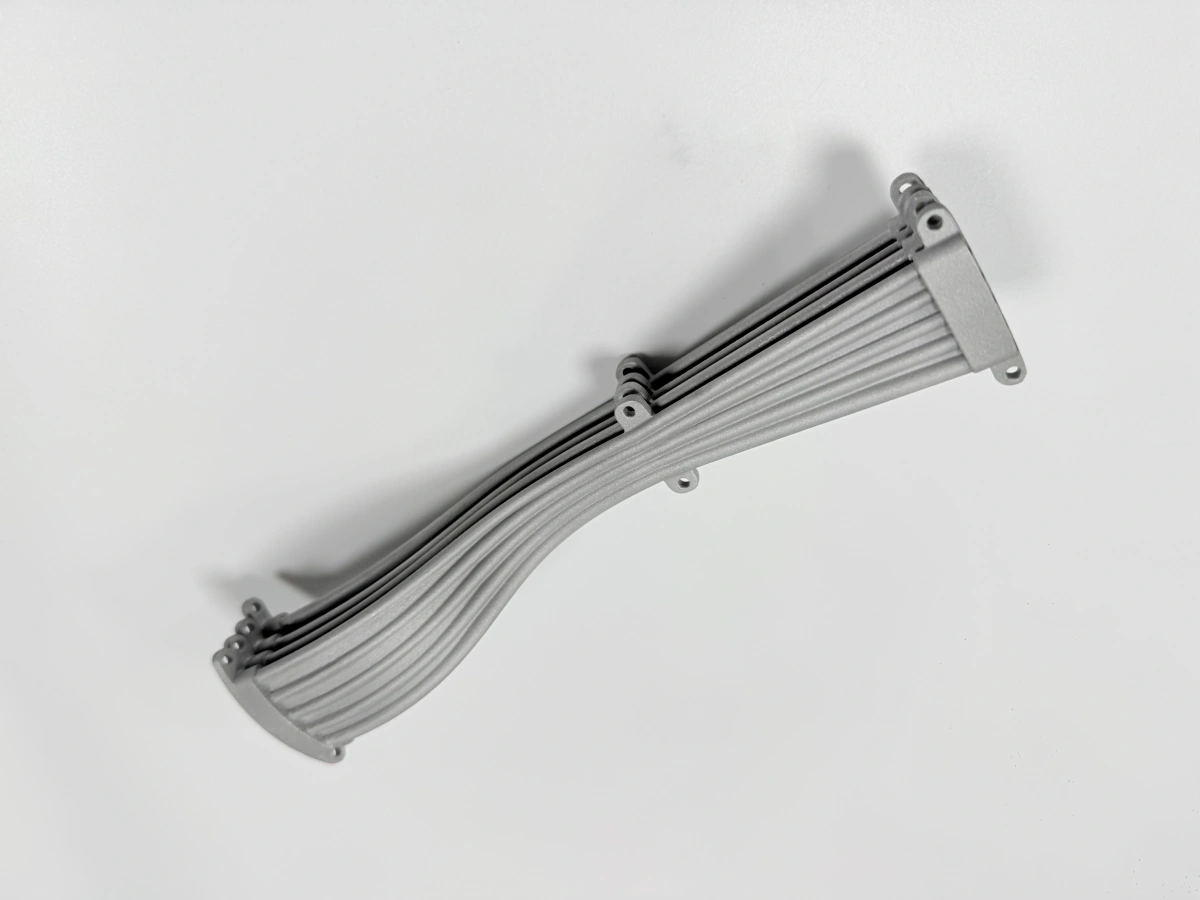
Thin walls are one of the most common risk features in 3D printed superalloy parts. During Powder Bed Fusion, thin sections experience rapid heating and cooling. If the wall is too thin, the part may have insufficient stiffness to resist thermal stress, support removal force, heat treatment distortion, or final machining vibration.
This risk is especially important for turbine vanes, nozzles, combustor liners, heat shields, and hot-gas path parts. These components often require thin-wall geometry for weight reduction, airflow, or thermal performance, but the same features can increase cracking, distortion, and inspection difficulty.
Thin-Wall Design Issue | Manufacturing Risk | Recommended Review |
|---|---|---|
Very thin airfoils | Edge distortion, cracking, and surface roughness variation. | Check minimum thickness, leading edge, trailing edge, and inspection method. |
Thin combustor walls | Thermal distortion and residual stress after printing. | Review support, heat treatment, and post-print dimensional inspection. |
Thin ribs or fins | Local overheating, vibration during finishing, or breakage during support removal. | Review orientation, support contact, and finishing allowance. |
Thin-wall internal channels | Powder trapping, blocked channels, and difficult defect inspection. | Confirm channel size, powder escape route, and CT or X-ray inspection needs. |
For more detailed thin-wall and thermal cycling design considerations, customers can review Designing Haynes 188 3D printed parts for thermal cycling, oxidation, and thin-wall structures.
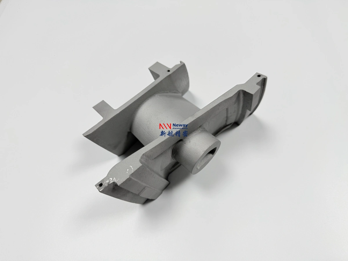
3. How Do Sharp Corners and Sudden Transitions Cause Cracks?
Sharp corners, notches, square internal edges, and sudden thickness transitions can concentrate stress in printed superalloy parts. During printing, each layer experiences repeated thermal expansion and contraction. Areas with abrupt geometry changes may accumulate local stress and become crack initiation points.
For hot-section components, sharp transitions can also create weak points during later Heat Treatment, machining, thermal cycling, or engine test conditions. Rounded transitions and smooth load paths are usually safer than sudden geometry changes.
Geometry Feature | Risk Mechanism | Design Improvement |
|---|---|---|
Sharp internal corners | Stress concentration during printing and service loading. | Add suitable fillets and avoid square internal corners where possible. |
Sudden wall thickness changes | Uneven cooling between thick and thin regions. | Use gradual transitions and local geometry smoothing. |
Notches or narrow grooves | Local crack initiation under residual stress or fatigue. | Review groove radius, machining method, and inspection access. |
Heavy boss connected to thin wall | Thermal mismatch and high local stress near the connection. | Add transition geometry, ribs, or redesign the local mass distribution. |
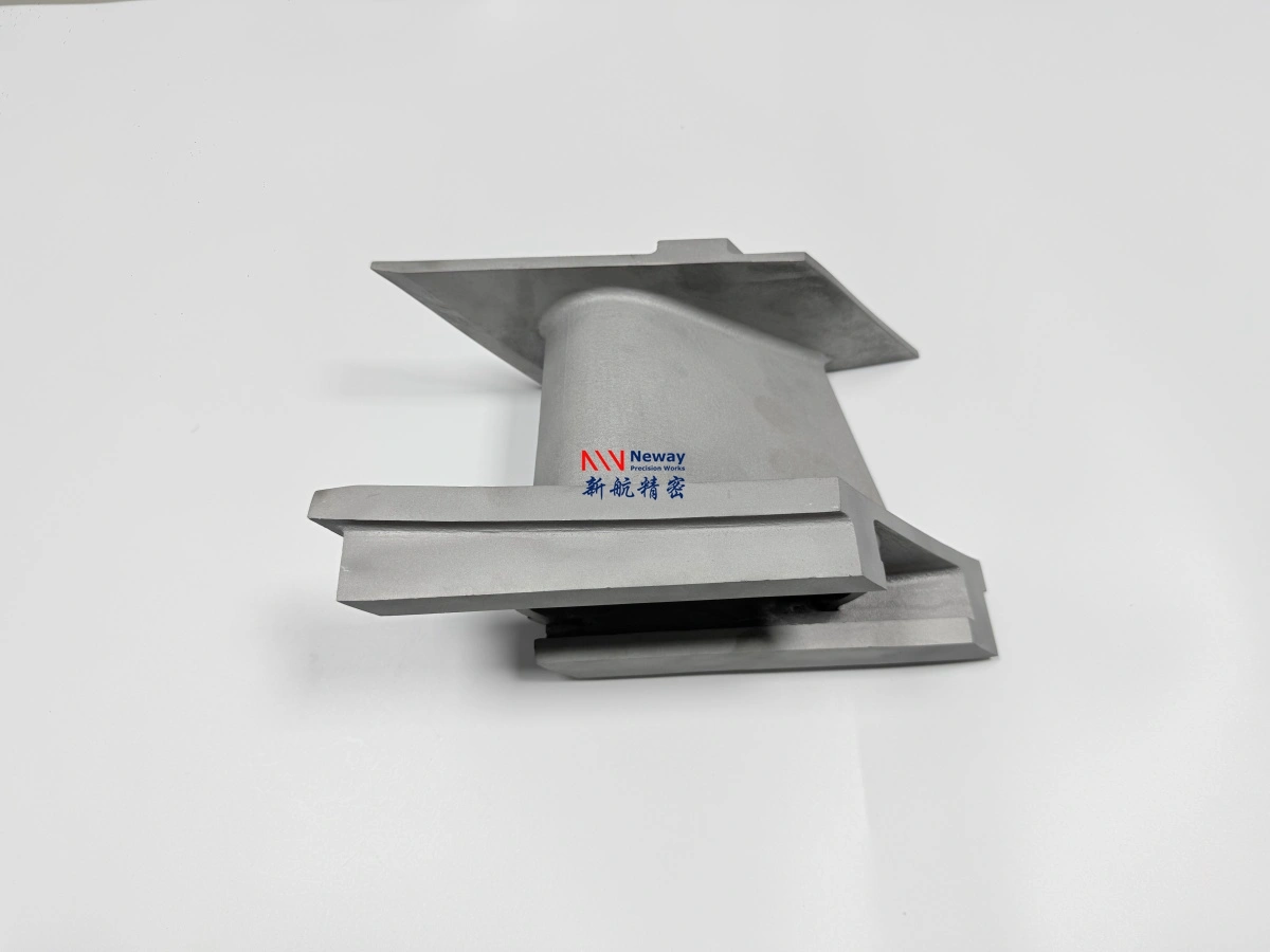
4. Why Do Overhangs, Cantilevers, and Large Flat Areas Matter?
Overhangs, long cantilever features, and large flat sections can increase cracking and distortion risk because they are harder to support and cool evenly. Poor support can cause local movement during printing, while large flat sections can accumulate residual stress and warp after support removal or heat treatment.
For superalloy parts, support design is not only used to hold the part. It also helps conduct heat away from the melt zone and stabilize geometry. If supports are too weak, too hard to remove, or placed in critical gas-path areas, the part may fail during production or require excessive finishing.
Feature | Possible Problem | Engineering Control |
|---|---|---|
Long cantilever | Warping, vibration, support failure, or cracking near the base. | Change build orientation or add temporary support features. |
Low-angle overhang | Poor surface quality, overheating, and weak underside geometry. | Optimize angle, add supports, or redesign the underside surface. |
Large flat plate | Residual stress accumulation and post-print warping. | Use ribs, contour changes, orientation optimization, or controlled stress relief. |
Unsupported thin edge | Edge curling, local cracking, and difficult finishing. | Review edge thickness, support layout, and post-processing method. |
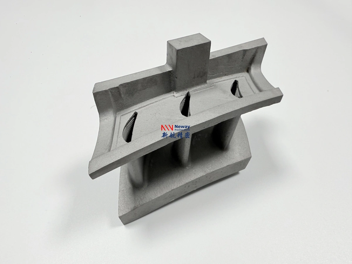
5. How Do Internal Channels and Closed Cavities Affect Crack Control?
Internal channels, enclosed cavities, and complex cooling passages are major reasons customers choose superalloy 3D printing. However, these features can also increase manufacturing risk because they may trap powder, restrict support removal, prevent visual inspection, and make internal defects harder to detect.
For hot-gas path parts, internal geometry should be reviewed for powder escape, cleaning access, minimum channel size, inspection access, and whether the internal structure can survive heat treatment or HIP without distortion. Hot Isostatic Pressing can help reduce internal porosity in selected applications, but it does not replace proper design review and defect inspection.
Internal Feature | Main Risk | Recommended Control |
|---|---|---|
Closed cavity | Trapped powder and no access for cleaning or inspection. | Add powder escape holes and define cleaning verification. |
Fine cooling channel | Powder blockage, rough internal surface, or incomplete inspection. | Review channel size, curvature, and CT inspection feasibility. |
Internal support requirement | Supports may be impossible to remove after printing. | Avoid unsupported internal overhangs or redesign channel orientation. |
Hidden crack-prone area | Defects may not be visible from outside the part. | Use X-ray, CT, FPI where applicable, and design for inspection access. |
6. Which Superalloy Materials Need Extra Crack-Risk Review?
Different superalloys have different additive manufacturing behavior. Some alloys are relatively mature for printing, while others require more careful feasibility review because of cracking tendency, heat treatment sensitivity, or hot-section application requirements.
For example, Managing cracking, distortion, and thin walls in Inconel 713C 3D printed superalloy parts is especially relevant when engineers are developing turbine vanes, nozzle parts, or hot-section prototypes in crack-sensitive materials.
Material Direction | Crack-Risk Review Focus | Typical Application |
|---|---|---|
Inconel 718 | Usually more mature, but still needs stress, heat treatment, and machining review. | Aerospace brackets, manifolds, structural parts, moderate hot-section parts. |
Inconel 625 | Usually reviewed for corrosion environment, distortion, and surface finish needs. | Nozzles, ducts, exhaust parts, chemical and marine components. |
Inconel 713C-class alloys | Require extra review for cracking, thin walls, thermal stress, and inspection. | Turbine vanes, nozzle prototypes, hot-section test parts. |
Haynes 188 / cobalt-based alloys | Reviewed for thermal cycling, oxidation, thin walls, and post-processing route. | Combustion hardware, hot-gas path parts, thermal test components. |
7. How Can Post-Processing and Inspection Reduce Crack-Related Risk?
Post-processing and inspection cannot fully compensate for a poor design, but they are essential for controlling crack-related risk in superalloy 3D printed parts. Stress relief, heat treatment, HIP evaluation, machining sequence, and non-destructive testing should be planned according to the part’s material, geometry, and application risk.
For crack-sensitive materials, customers can also review What Post-Processing Controls Are Needed for Inconel 713C 3D Printed Parts? to understand how stress relief, heat treatment, HIP, machining, EDM, and inspection are connected.
Control Method | What It Helps Control | When It Is Important |
|---|---|---|
Stress relief | Residual stress, distortion, and crack growth after printing. | Before support removal or precision machining. |
Heat treatment | Microstructure, stability, and mechanical property control. | For high-temperature or functional superalloy parts. |
HIP evaluation | Internal porosity and internal quality improvement. | For fatigue-sensitive, pressure-loaded, or high-value hot-section parts. |
X-ray inspection | Internal defects and selected crack or porosity indications. | For high-value parts or simplified internal geometry. |
CT inspection | Internal channels, powder residue, cracks, porosity, and complex internal geometry. | For enclosed cavities, cooling channels, and complex hot-section parts. |
Metallographic review | Microstructure, heat treatment condition, and process validation. | For qualification, failure analysis, or high-temperature material validation. |
For inspection planning, customers may also refer to X-Ray Inspection: Rapid Internal Defect Screening for AM Parts and Metallographic Microscopy: Microstructure & Heat-Treat Validation.
8. What RFQ Data Helps Review Cracking Risk?
To review cracking risk before quotation, customers should provide both geometry and application data. The supplier needs to understand not only the alloy name, but also where stress, temperature, load, and inspection requirements are concentrated.
RFQ Data | Why It Helps Crack-Risk Review |
|---|---|
3D CAD file | Used to evaluate wall thickness, overhangs, sharp transitions, cavities, and support access. |
2D drawing | Defines tolerances, datums, critical surfaces, machining zones, and inspection requirements. |
Material requirement | Confirms whether the selected superalloy has known crack sensitivity or special heat treatment needs. |
Minimum wall thickness | Important for thin-wall stability, distortion, powder removal, and crack control. |
Operating temperature | Helps evaluate thermal stress, oxidation exposure, and hot-section suitability. |
Thermal cycling condition | Repeated heating and cooling can increase crack growth and fatigue risk. |
Load and pressure condition | Helps identify structural, fatigue-sensitive, or pressure-loaded areas. |
Inspection standard | Determines whether visual inspection, FPI, X-ray, CT, CMM, or metallographic validation is needed. |
9. Summary
Design features that increase cracking risk in 3D printed superalloy parts include thin walls, sharp corners, sudden thickness changes, long unsupported overhangs, enclosed cavities, narrow internal channels, large flat areas, heavy local masses, and difficult-to-inspect hidden structures. These features can create thermal stress, residual stress, uneven cooling, distortion, powder removal problems, and inspection limitations.
To reduce cracking risk, superalloy parts should be reviewed before production for wall thickness, fillet design, smooth transitions, build orientation, support removal, powder cleaning, heat treatment, HIP evaluation, machining sequence, and inspection access. Customers should provide CAD files, drawings, material requirements, operating conditions, load information, thermal cycling details, and inspection standards so the correct crack-control strategy can be developed before quotation.