Designing Haynes 188 3D Printed Parts for Thermal Cycling, Oxidation, and Thin-Wall Structures
Designing Haynes 188 3D Printed Parts for Thermal Cycling, Oxidation, and Thin-Wall Structures
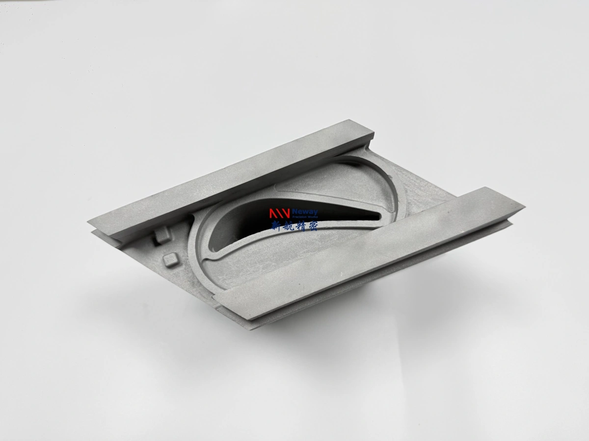
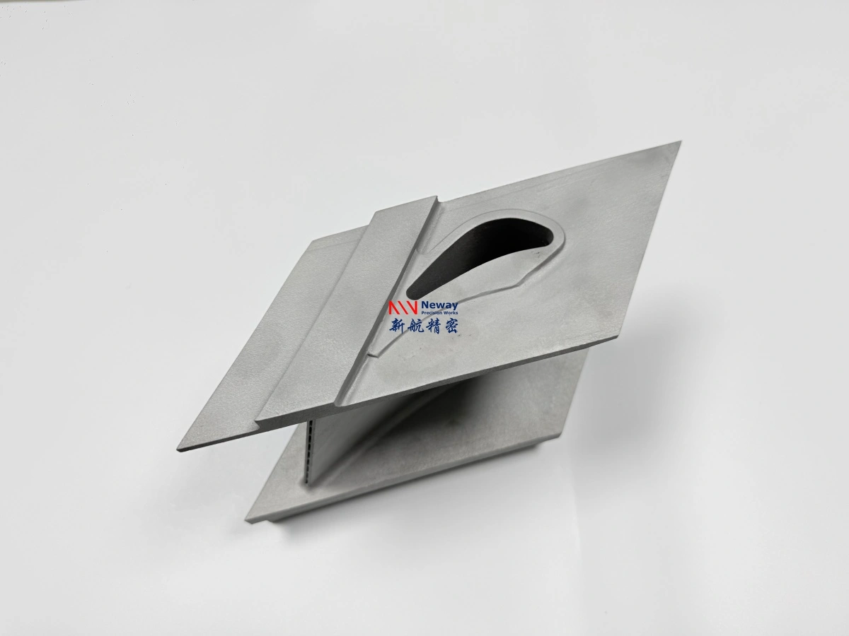
Haynes 188 thin wall 3D printing is used for hot-section components that must handle thermal cycling, high-temperature oxidation, hot-gas exposure, and complex geometry. Because Haynes 188 is a cobalt-based superalloy used for severe combustion and hot-gas path environments, the design stage is critical. A poorly designed part may require excessive support, deform during printing or heat treatment, trap powder inside channels, or fail to meet final machining and inspection requirements.
At Neway3DP, we manufacture Haynes 188 3D printed parts for combustion hardware, nozzles, heat shields, flame tubes, hot-end brackets, aerospace thermal structures, and energy equipment components. Our engineering support covers design-for-additive-manufacturing review, powder bed fusion printing, heat treatment, CNC machining, EDM, surface treatment, and inspection planning.
For engineers designing custom Haynes 188 thin wall parts, the key is to consider manufacturability and service environment together. Wall thickness, support strategy, internal channel access, machining allowance, heat treatment sequence, oxidation exposure, thermal cycling, and inspection requirements should be defined before production begins.
Why DfAM Matters for Haynes 188
Design for additive manufacturing matters because Haynes 188 is a high-value superalloy and the cost of design mistakes can be significant. Unlike simple polymer prototypes or low-cost metal parts, Haynes 188 components are usually used in demanding combustion, aerospace, turbine, or energy applications. If the design is not suitable for powder bed fusion, the project may face higher cost, longer lead time, deformation risk, difficult support removal, or poor final surface quality.
For powder bed fusion 3D printing, the CAD model should be reviewed for build orientation, support requirements, thin-wall stability, powder removal, post-machining allowance, and inspection access. Good DfAM planning helps reduce manufacturing risk and improves the chance of delivering functional hot-section components.
DfAM Issue | Potential Risk | Recommended Design Action |
|---|---|---|
Unsupported thin walls | Warping, vibration during processing, or dimensional movement | Review wall thickness, add ribs where needed, and avoid long unsupported spans |
Support-heavy geometry | Higher cost, difficult support removal, and rough supported surfaces | Optimize build orientation and move supports away from critical surfaces |
Closed internal cavities | Trapped powder and cleaning difficulty | Add powder removal holes and inspection access where possible |
No machining allowance | Critical holes, threads, and sealing faces may not meet final tolerance | Reserve stock on datum surfaces, holes, flanges, and sealing areas |
Unclear inspection requirements | Late-stage cost increase or documentation mismatch | Define CMM, 3D scan, X-ray, CT, FAI, or material certificate needs before quotation |
Thin-Wall Structure Design
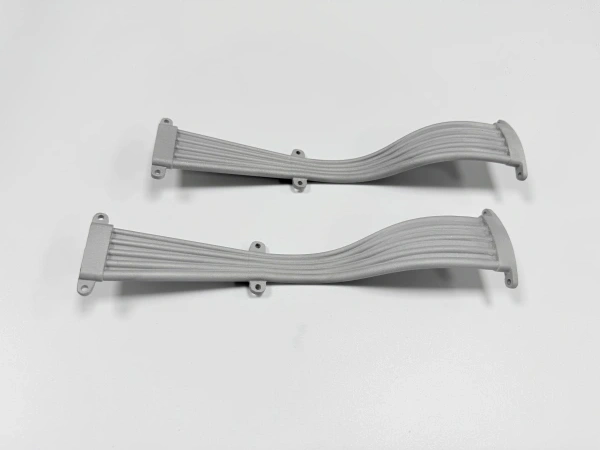
Thin wall cobalt superalloy 3D printing can be valuable for combustion liners, heat shields, hot-gas ducts, flame tubes, and lightweight thermal structures. However, thin walls are also more sensitive to residual stress, heat input, support removal, and thermal distortion. The design must balance lightweight performance with enough stiffness and manufacturability.
For Haynes 188 hot-section parts, thin walls should be designed with smooth transitions, adequate fillets, local reinforcement, and clear load paths. Sudden thickness changes, sharp internal corners, and long unsupported surfaces can increase stress concentration and deformation risk during printing, heat treatment, or service.
Thin-Wall Design Area | Design Recommendation | Reason |
|---|---|---|
Wall thickness | Avoid extremely thin walls unless reviewed by engineering | Very thin walls may deform during printing, heat treatment, or support removal |
Reinforcing ribs | Add ribs or local stiffening features where geometry is flexible | Improves stiffness and reduces distortion risk |
Transition areas | Use smooth transitions and generous fillets instead of sharp thickness changes | Reduces stress concentration and thermal fatigue risk |
Large flat panels | Use curvature, ribs, beads, or controlled supports when possible | Large flat hot-section surfaces are more likely to warp |
Thermal exposure zones | Identify areas facing direct hot gas or repeated thermal cycling | Helps plan wall thickness, surface finishing, and inspection priority |
Internal Channels and Powder Removal
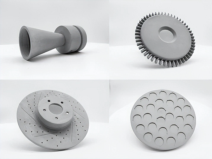
Internal channels are one of the main reasons engineers choose Haynes 188 additive manufacturing. Cooling channels, hot-gas passages, vent holes, and internal flow paths can be built directly into the part. However, every internal channel must be designed with powder removal and inspection in mind.
Blind cavities, long narrow channels, closed pockets, and sharp turns can trap powder after printing. If the part is used in combustion or thermal cycling environments, trapped powder or blocked channels may affect performance and safety. Cleaning holes, powder drainage paths, and inspection access should be designed before the model is released for quotation.
Internal Feature | Potential Risk | Design Recommendation |
|---|---|---|
Cooling channels | Powder may remain inside if the channel is too narrow or inaccessible | Provide inlet and outlet access for cleaning and inspection |
Blind cavities | Trapped powder may be impossible to remove completely | Avoid blind cavities or add cleaning holes where possible |
Long curved passages | Cleaning tools and inspection methods may have limited access | Review channel diameter, curvature, and cleaning path before printing |
Thin internal webs | May deform or trap partially fused powder | Check feature thickness and support-free printability |
Critical flow paths | Blocked or rough channels may affect flow performance | Consider CT inspection, flow testing, or design modification if needed |
Support Strategy for Haynes 188 Hot-Section Parts
Support strategy is critical for Haynes 188 hot-section parts because supports affect thermal control, deformation risk, surface quality, and finishing cost. Supports help anchor the part during printing and manage heat, but they also create contact marks and require access for removal.
For combustion and hot-gas path parts, supports should be placed away from sealing faces, flow surfaces, visible surfaces, and areas exposed to critical thermal loads whenever possible. The design should also provide enough space for support removal tools so the part is not damaged during post-processing.
Support Planning Area | Design Concern | Recommended Action |
|---|---|---|
Support location | Support marks may damage functional or flow-facing surfaces | Place supports on non-critical or post-machined areas where possible |
Support removal access | Hidden supports may be difficult or impossible to remove cleanly | Provide tool access and avoid enclosed support zones |
Thin-wall support | Support removal may deform or damage thin features | Use controlled support density and review removal sequence |
Thermal stress control | Insufficient supports may increase warping risk | Balance support reduction with distortion control |
Critical surfaces | Supported surfaces may need extra finishing | Reserve machining allowance or redesign orientation for functional surfaces |
Machining Allowance for Critical Features
As-printed Haynes 188 parts are near-net-shape components, not fully finished precision parts. Critical assembly surfaces, sealing faces, threaded holes, locating holes, flange faces, and datum surfaces usually require CNC machining after printing.
Because Haynes 188 is a difficult-to-machine superalloy, machining allowance should be used strategically. Adding machining stock to every surface may increase cost significantly, while failing to reserve stock on critical features can prevent the part from meeting final tolerance. The best approach is to define critical surfaces clearly on the 2D drawing.
Critical Feature | Why Allowance Is Needed | Recommended Planning Method |
|---|---|---|
Assembly face | Controls flatness, alignment, and contact quality | Add machining allowance and define datum requirements |
Sealing face | Requires controlled roughness and flatness | Specify surface finish, flatness, and inspection method |
Threaded holes | Printed threads are usually not suitable for reliable fastening | Print pilot features and finish by tapping, thread milling, or inserts |
Locating holes | Require accurate diameter, roundness, and positional control | Print undersized and finish by drilling, reaming, boring, or EDM |
Flange faces | May need controlled flatness and bolt-hole alignment | Define flange flatness, hole tolerance, and sealing requirements |
EDM for Small Holes, Slots, and Delicate Features
Some Haynes 188 features are difficult to finish by conventional machining, especially small holes, narrow slots, thin-wall openings, deep features, and delicate flow paths. In these cases, electrical discharge machining can be used together with CNC machining.
EDM is useful because it can machine hard superalloy features with less mechanical cutting force. For nozzles, flame tubes, hot-gas structures, and combustion-related parts, EDM can help create precise holes, slots, vents, and flow openings that would be difficult to produce directly by printing or conventional cutting.
EDM Feature | Why EDM Helps | Typical Haynes 188 Application |
|---|---|---|
Small holes | Improves hole accuracy where drilling may be difficult | Nozzles, cooling holes, vent holes, combustion features |
Narrow slots | Creates thin openings with lower mechanical cutting force | Thermal fixtures, flow structures, hot-end components |
Thin-wall openings | Reduces risk of deforming delicate printed structures | Combustion liners, heat shields, hot-end housings |
Complex profiles | Supports difficult profiles and hard-to-access regions | Flow-directing structures, thermal hardware, custom hot-section parts |
Heat Treatment and Distortion Control
Haynes 188 printed parts may require heat treatment service to relieve stress, stabilize the structure, and reduce deformation risk before final machining or service. Heat treatment should be planned together with support removal, machining sequence, and inspection requirements.
For thin-wall hot-section structures, distortion control is especially important. A part may look printable in CAD but still move during stress relief, support removal, CNC machining, or thermal cycling. The manufacturing sequence should be reviewed before quotation to reduce dimensional risk.
Distortion Control Factor | Why It Matters | Recommended Control Method |
|---|---|---|
Build orientation | Affects residual stress, support volume, and thermal behavior | Review orientation for both printability and final machining |
Stress relief | Reduces internal stress before machining or final use | Apply project-defined heat treatment where required |
Support removal sequence | Improper removal may release stress unevenly | Use a controlled removal plan for thin-wall structures |
Machining sequence | Machining may release stress or distort flexible features | Machine datums and critical faces after stress relief where possible |
Thermal cycling service | Repeated operation may reveal hidden distortion or stress issues | Share thermal cycle details before material and process planning |
Inspection Planning for Haynes 188 Designs
Inspection planning should be included at the design stage, especially for thermal cycling 3D printed superalloy parts with thin walls, internal channels, sealing faces, and critical mounting features. If inspection access is not considered early, it may be difficult to verify internal quality or critical dimensions after production.
Common inspection methods include CMM inspection, 3D scanning, X-ray inspection, CT inspection, first article inspection, material certificate review, heat treatment records, and surface roughness measurement. The inspection plan should match the part’s risk level and application environment.
Inspection Method | Purpose | Recommended For |
|---|---|---|
CMM inspection | Checks datums, holes, flanges, and machined interfaces | Assembly-ready parts and tight-tolerance features |
3D scanning | Compares complex freeform geometry against CAD data | Thin-wall housings, heat shields, flow-directing structures |
X-ray inspection | Checks selected internal defects or hidden structural issues | Critical hot-section components and qualification-sensitive parts |
CT inspection | Verifies internal channels, hidden cavities, powder removal, and defect risk | Internal cooling channels, complex nozzles, combustion structures |
FAI | Documents first article dimensions before repeat production | Prototype approval, pilot batch, and production-intent projects |
RFQ Design Checklist for Haynes 188 Thin Wall Parts
To quote custom Haynes 188 thin wall parts accurately, the supplier needs to understand both the geometry and the service environment. A 3D model helps review build orientation, supports, wall thickness, channels, and powder removal. A 2D drawing confirms tolerances, critical surfaces, machining allowance, heat treatment, and inspection requirements.
For faster quotation and manufacturability review, please provide the following information:
3D CAD model, preferably STEP, X_T, IGS, or STL format
2D drawing with material grade, tolerances, datum requirements, threads, flanges, sealing surfaces, surface finish, and inspection notes
Required material, such as Haynes 188, GH5188, or an approved equivalent
Critical surfaces that require CNC machining or EDM finishing
Wall thickness requirements and any areas exposed to direct hot gas
Internal channel details, powder removal paths, and cleaning access
Working temperature, peak temperature, thermal cycling condition, oxidation environment, pressure, vibration, fatigue, or corrosion exposure
Required post-processing, such as heat treatment, CNC machining, EDM, blasting, polishing, coating, or surface treatment
Inspection requirements, such as dimensional report, CMM report, 3D scan, FAI, CT inspection, X-ray inspection, material certificate, heat treatment record, or tensile test
Target delivery schedule and shipping destination
Why Work with Neway3DP for Haynes 188 DfAM Support?
Neway3DP supports Haynes 188 design for additive manufacturing support from early CAD review to final delivery. Our team can help evaluate whether the design is suitable for powder bed fusion, whether thin walls or internal channels create manufacturing risk, and which surfaces need machining allowance or inspection planning.
For aerospace and aviation 3D printing and energy and power applications, this early review helps customers reduce redesign risk and move from prototype to functional hot-section validation more efficiently.
FAQ