What Are The 3D Printing Technologies Used for Copper Parts Additive Manufacturing?
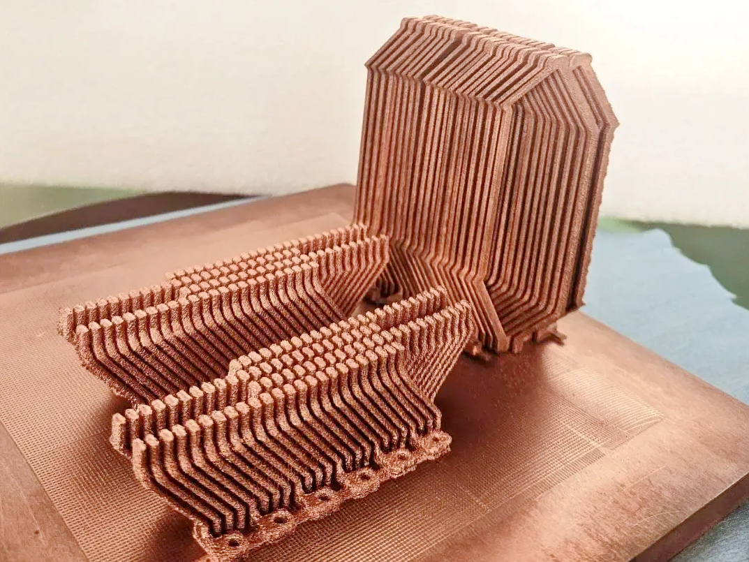 Copper 3D printing is a route-selection problem governed by conductivity, heat flow, alloy strength, geometry, quantity, and the final inspection state. Laser powder bed fusion, electron beam melting, directed energy deposition, and binder jetting can all be considered, but they do not deliver interchangeable copper conditions. The main limitation is copper's high reflectivity and thermal conductivity: a process window that produces a dense-looking coupon may still fail an electrical, thermal, pressure, or fatigue requirement on the actual part. Select the alloy, machine, thermal route, surface condition, and verification method as one qualified package, and release it only when the final part passes the defined application test.
Copper Material and Final State
Pure or nearly pure copper is normally selected when electrical or thermal conductivity has priority. C101 and C110 can be screened for busbars, contacts, cold plates, coils, and heat exchangers, but the quoted conductivity must state the material condition, measurement method, and part location. CuCr1Zr trades some conductivity for higher strength and better elevated-temperature stability. GRCop-42 belongs to a separate high-temperature copper-alloy discussion and requires its own powder, heat-treatment, and service validation. A grade name is not an acceptance value for a printed part.
Define whether the delivered part is as-built, stress relieved, heat treated, machined, plated, or coated. Heat treatment can change hardness, strength, conductivity, and dimensions. Machining can improve a contact face or sealing datum, but it does not remove internal lack of fusion or prove the integrity of a cooling channel. The copper alloy 3D printing route should therefore be quoted with the required final state and the test condition attached.
Laser Powder Bed Fusion for Copper
Laser powder bed fusion, including commercial DMLS or SLM terminology, melts thin layers of copper powder with a scanned beam. Copper reflects much of the energy from a conventional infrared laser and conducts heat away from the melt pool quickly. Laser wavelength, power density, scan speed, hatch overlap, layer thickness, preheating, atmosphere, and powder morphology therefore influence melt-pool stability and lack-of-fusion risk. A powder bed fusion route is often screened for low-volume cold plates, conformal channels, coils, and consolidated assemblies where the geometry saves tooling or joints.
LPBF can provide fine features, but the design still needs powder-removal openings, support access, machining allowance, and a surface plan. Internal channel performance depends on hydraulic diameter, roughness, trapped powder, leak paths, and the ability of CT or a pressure test to examine the actual passage. A nominal machine resolution is not a tolerance. Finish critical datums with an agreed CNC machining route when the drawing requires it. For an electrical contact, measure resistance on the finished contact surface; for a thermal part, test heat transfer with the specified coolant, flow, mounting, and boundary condition.
Electron Beam Melting and Vacuum Boundaries
Electron beam melting uses a beam in a vacuum and normally maintains a warmer powder bed than a laser process. This thermal history may reduce some thermal-gradient and distortion risks for a qualified copper alloy, while the vacuum can limit oxidation during melting. It does not guarantee high conductivity, a smooth surface, or aerospace approval. Beam calibration, powder chemistry, charging behavior, surface roughness, powder removal, and the selected post-processing route remain part of the qualification.
EBM may be screened for a larger copper heat-transfer structure or propulsion-related component when the machine and alloy have supporting evidence. It is a weaker fit when small electrical features, tight machined datums, or a very smooth channel surface dominate the requirement. Compare EBM against LPBF using the actual geometry, thermal cycle, inspection resolution, and final surface, not a universal statement that vacuum is better.
Directed Energy Deposition and Copper Repair
Directed energy deposition feeds copper wire or powder into a moving melt pool. Heat input, travel speed, shielding, overlap, dilution, substrate preparation, and interpass temperature control the bond and the heat-affected zone. DED can be useful for adding material to a large copper feature, restoring a worn contact or tooling surface, or producing a near-net shape that will be machined. It is not a substitute for LPBF when the part depends on fine internal channels or small isolated features.
A copper repair plan should define the parent alloy, minimum remaining wall, surface preparation, allowable dilution, thermal limits, machining allowance, and the required electrical, thermal, bond, or pressure result. Lack of fusion at the repair boundary may require removal and redeposition rather than polishing. Cross-section microscopy, hardness mapping, conductivity measurement, dimensional inspection, and a representative repair coupon can support disposition when the design authority approves the method.
Binder Jetting and Sintering
Binder jetting prints a liquid binder into a copper powder bed and creates a fragile green body. Debinding removes the binder; sintering creates metallurgical bonding and causes shrinkage. The route can be attractive for repeat batches because an entire layer is patterned without a melt pool, but final conductivity and density depend on powder packing, debinding, furnace atmosphere, peak temperature, heating rate, part loading, and shrinkage uniformity. A batch quote should use accepted sintered units, not green-body count.
Binder jetting may suit a family of housings, brackets, or non-pressure thermal components when a validated shrinkage map and furnace recipe are available. It needs caution for thin channels, pressure boundaries, high-current contacts, and parts that require tight as-sintered datums. Verify final dimensions, density or open porosity, conductivity, surface condition, and leak performance where relevant. CNC machining can finish the interface, but it cannot compensate for a nonuniform sintered core.
Copper Process Decision Matrix
Route | When to screen it | Main copper-specific condition | Release evidence |
|---|---|---|---|
LPBF or SLM | Low-volume complex channels, coils, cold plates, and consolidated assemblies | Laser absorption, melt-pool stability, powder removal, and support access | Conductivity or resistance, thermal test, CT or sectioning, and final dimensions |
EBM | Large heat-transfer geometry with a qualified vacuum route | Beam calibration, vacuum record, roughness, charging, and powder removal | Geometry-representative thermal, surface, defect, and dimensional evidence |
DED | Large features, added material, or localized repair | Parent alloy, dilution, heat-affected zone, and machining transition | Bond inspection, conductivity, sectioning, dimensions, and repair disposition |
Binder jetting | Repeat batches with a stable sintering and shrinkage model | Powder packing, debinding, furnace atmosphere, density, and accepted yield | Final density, conductivity, dimensions, and leak or functional test |
Applications and Buyer Decisions
For an automotive EV cold plate with branched channels, LPBF may be selected because it can integrate the channel network and reduce joints. The risk is trapped powder, roughness, and leakage, so the RFQ must specify coolant, flow, pressure, leak rate, thermal load, and channel inspection. For an electronics high-current busbar or contact, C101 or C110 may be screened because conductivity is primary; the release plan should measure contact resistance and inspect the machined interface rather than rely on bulk density alone.
For an aerospace heat exchanger or propulsion liner, CuCr1Zr or GRCop-42 may be compared when strength retention and thermal cycling matter. The choice requires alloy-specific heat treatment, thermal-fatigue evidence, and an approving authority. For an industrial repeat batch of copper housings, binder jetting may be economical only if the sintered yield, dimensional compensation, conductivity, and inspection cost are known. These examples show why application, alloy, route, quantity, and risk must be decided together.
Failure Modes and Verification
Reflectivity and rapid heat conduction can destabilize a laser melt pool and leave lack of fusion or keyhole porosity. Control the qualified parameter set, powder chemistry, powder size distribution, oxygen level, and build record; inspect with CT or metallography when the defect size is detectable by that method. Oxide or contamination can reduce conductivity or bond quality, so control storage, handling, atmosphere, and surface preparation. Sintering cracks and nonuniform shrinkage require furnace-profile control, witness parts, and final-state dimensional inspection.
Use ASTM E1004 as a possible reference for electrical-conductivity measurement and ASTM E8/E8M for tensile testing only when the project specification accepts those methods. ASTM F3122 may provide a reference framework for metal additive-manufacturing material evaluation. A thermal test must state coolant, flow, mounting, heat input, and temperature measurement locations. A pressure or leak test must state pressure, hold time, fluid, temperature, and acceptance limit. If a result falls outside the approved criterion, hold the part and obtain engineering disposition; do not convert a coupon result into automatic product approval.
Copper RFQ and Release Path
Provide the CAD and drawing revision, copper grade or approved alternatives, electrical or thermal target, quantity, geometry and channel dimensions, wall thickness, load or pressure, coolant or fluid, temperature cycle, surface and contact requirements, final heat-treatment or machining state, inspection method, documentation, and delivery milestone. State whether the need is a prototype, repair, low-volume functional part, or repeat batch. The supplier can then compare LPBF, EBM, DED, binder jetting, and conventional machining with a reason tied to conductivity, geometry, quantity, risk, and accepted output.
Before release, request powder or wire lot traceability, machine and parameter records, furnace or heat-treatment records, dimensional results, conductivity or thermal data, defect inspection, pressure or leak results where required, and disposition of deviations. Copper 3D printing is valuable when the final part meets the specified electrical, thermal, mechanical, and geometric conditions with evidence that represents the actual route.
FAQs
Which 3D printing technology is best for copper parts in electronics applications?
What copper materials are commonly used in Selective Laser Melting (SLM)?
How does Electron Beam Melting (EBM) benefit copper parts for aerospace applications?
Can Binder Jetting produce copper parts, and what are its advantages?
What is the role of copper alloys in additive manufacturing for automotive components?