Stainless Steel Cast Manifolds: What the Cast Route Adds
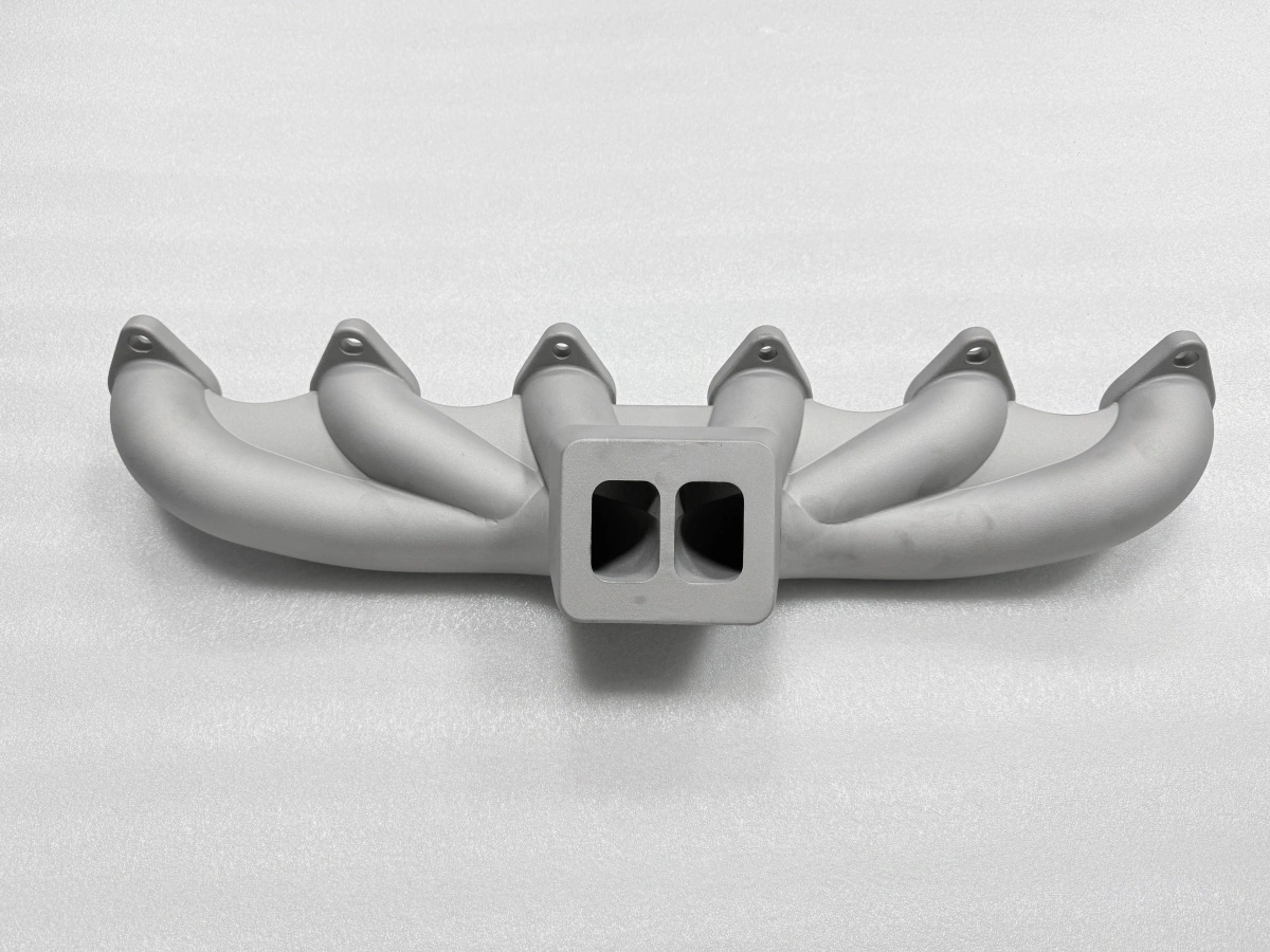
A stainless steel casting pays for itself when one part carries the curve, the wall and the flange at 1.0 mm. Austenitic stainless pours well, holds useful strength to about 800 °C and keeps a passive surface in exhaust condensate, so one casting can replace a weldment with five joints and a stress relief. The route loses that place when the shape is a straight tube, the batch is tiny, or the duty cycle exceeds the alloy's scaling limit.
Why choose a stainless steel cast manifold?
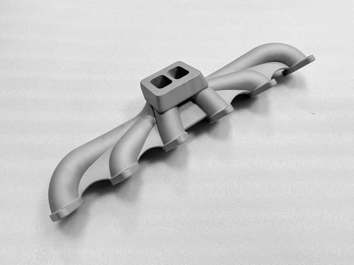
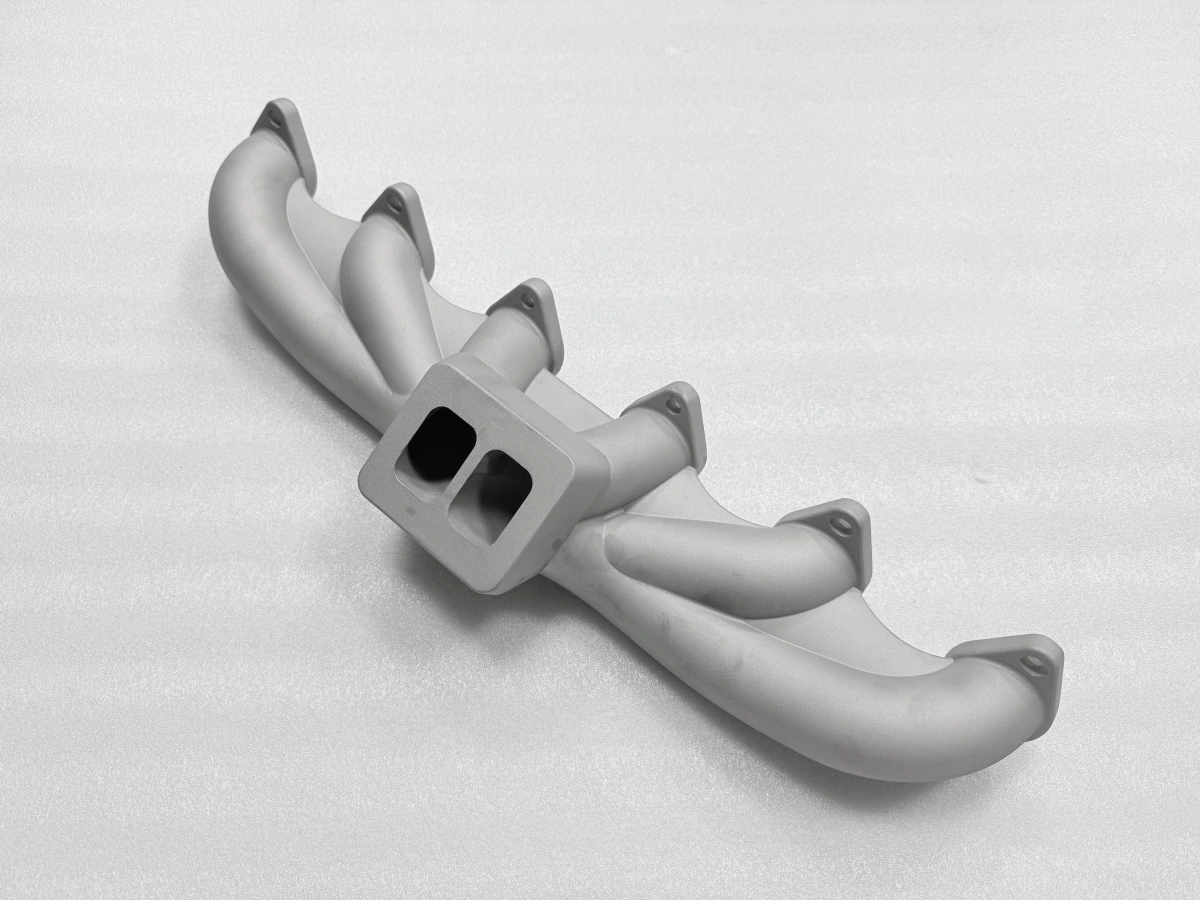
The cast route wins on shape first. A manifold with runners leaving one log at compound angles is one casting, not five cut tubes and five welds, and every weld removed is a leak path and an inspection point that no longer exists.
It wins on section control second. The same casting can carry a 10 mm boss around a bolt hole and a 1.0 mm wall between runners without a joint. A fabricated part has to pick a tube wall and reinforce it locally, and that reinforcement is usually another weld.
Alloy choice follows the duty cycle, not the drawing. A 304 or 316 type pours well and handles exhaust gas to about 800 °C; a 309 or 310 type holds scale resistance above 1,000 °C at the cost of machinability; duplex and precipitation-hardening grades buy corrosion resistance or strength and charge for it in pour window and cooling control.
The RFQ should state the duty cycle, not only the alloy name. Batch size decides the rest. A printed pattern plus a standard shell schedule makes a first article in days, and the fixed cost is spread across a run of ten to a few hundred pieces. Below ten pieces the setup sits on every part; above a few hundred, tooling and machining usually take over.
What does the cast structure change?
Cast structure changes how the alloy behaves at the flange and in the wall. An austenitic stainless casting solidifies with a coarse dendritic grain and a small, controlled ferrite content, and that mix sets the yield strength, the ductility and the response to welding if a repair is needed.
Porosity is the second difference. A sound casting holds gas porosity below the level that shows on a machined seal face, and the foundry controls it through pouring temperature, shell preheat and feeding rather than through a later press. A printed part controls the same property through laser energy density and, when needed, hot isostatic pressing.
Dimensional behavior is the third. As-cast tolerances sit in the CT5–CT7 band of ISO 8062-3 for a manifold-sized part, which is why every functional surface keeps stock. That band is a property of the process, not a defect, and a drawing that asks for IT7 straight from the mold is asking the wrong route.
The mechanism behind the wall movement is covered in a separate knowledge article. The wall is the fourth. A 1.0 mm cast wall in a curved runner is stable when the section is supported by a flange and a rib, and it is the first place that warps when the shell schedule is wrong. The casting route gives the thin wall, but it also makes the wall the feature that needs the most process discipline.
How much stock does machining need?
Machining stock is set by the feature, not by habit. A flange face that will be faced and sealed needs 1.0–2.0 mm, a port bore that will be drilled and threaded needs 1.0–1.5 mm, and a face that stays as-cast needs no stock at all.
Too little stock is the expensive error. A flange that arrives 0.3 mm under the finished height cannot be saved by a better setup; it becomes a scrap part, and the loss is the whole casting rather than the facing operation.
Too much stock is the quieter error. An extra 2 mm on a thin flange raises the interrupted cut, adds a second pass and can pull the face out of flatness after the part has already been stress relieved.
Flatness and roughness belong in the same table as the stock. The target is 0.05 mm on the twin-port flange, the acceptance band is 0.05–0.10 mm, and the sealed face is finished to Ra 1.6–3.2 µm under ISO 4287.
Feature | Condition | Target | Band (unit) |
|---|---|---|---|
Flange face stock | Stainless steel casting, faced and sealed | 1.5 mm | 1.0–2.0 mm |
Port bore stock | Drilled and threaded after casting | 1.2 mm | 1.0–1.5 mm |
Flange flatness | Twin-port flange, after stress relief | 0.05 mm | 0.05–0.10 mm |
Seal face roughness | Faced surface, ISO 4287 | Ra 1.6 µm | Ra 1.6–3.2 µm |
Which heat treatment fits?
Stress relief is the treatment that fits a cast stainless manifold, and it belongs after knockout and before machining. The part is held at 850–950 °C for 1.5–2 h, then cooled in the furnace to about 300 °C before air cooling, a cycle described for austenitic castings in ASM Handbook Vol. 7.
The order matters more than the setpoint. Stress relief before knockout does not remove the constraint of the shell, and stress relief after machining moves the distortion into the finished part. The cycle sits between the two, and the flange is measured again afterward because flatness can move during the relief.
Knock out the shell and cut the part from the tree; let it cool in air.
Load the part for stress relief at 850–950 °C and hold for 1.5–2 h.
Cool in the furnace to about 300 °C, then air cool to room temperature.
Re-check flange flatness and wall thickness before the part is released to machining.
A stress relief that is skipped shows up later as a flange that moves after facing. A relief that is run too hot or too long can coarsen the structure and soften the surface, which is why the cycle is written with a temperature band and a hold time rather than a single number.
When is the printed route better?
The printed route is better in two clear cases. The first is a single part or a design that is still moving: a powder bed fusion (PBF) build needs no pattern, so a 1.0 mm wall and an internal channel can be changed in the file and reprinted in days, while a casting waits for a pattern and a shell.
The second is a shape that casting cannot feed. A runner with a deep internal cavity or a wall that changes section every 20 mm is easier to grow layer by layer than to feed through a shell, and the printed part can be stress relieved and machined on the same flange faces.
The cast route is better in two other cases. The first is a stable design at ten to a few hundred pieces: the pattern is amortized, the shell schedule is fixed, and the piece price falls below a printed part that is built one at a time.
The second is a large, simple manifold where the alloy and the section do the work. A casting can carry a 1.0 mm wall over a 300 mm runner and a 10 mm boss in the same part, and it does so without the residual stress pattern of a multi-pass weld or the build-time cost of a tall PBF part.
A documented recovery path exists for a warped first casting, and it starts with a new pattern rather than a straightened part. The comparison is not a tie. Printing removes the pattern and shortens the first article; casting removes the weld and lowers the piece price at volume. A manifold program usually starts on one route and moves to the other when the design freezes or the batch grows.
When does the material judgment not hold?
The judgment fails above the alloy's scaling limit. A 304 or 316 type in continuous service above about 800 °C scales and loses section, and the answer is a heat-resistant grade or a nickel alloy, not a thicker wall of the same steel.
It fails in the wrong corrosion environment. Chloride-bearing condensate attacks the austenitic grades at the weld and under deposits, and a duplex or a higher-molybdenum grade is the material answer before the route answer.
It fails below the wall limit. A cast wall under about 0.8 mm is difficult to fill and difficult to inspect, and a printed wall in the same range needs a qualified parameter set; the material judgment assumes the wall can be made sound.
It fails when the tolerance is tighter than the process. A bore that needs IT7, a port position within 0.05 mm or a flatness below the CT5–CT7 band belongs in machining after the casting, and the material choice does not change that.
It fails when the batch cannot absorb the setup. Two or three parts carry the pattern, the shell and the inspection plan on every piece, and a fabricated or printed part is the cheaper answer even when the casting is technically sound. Send the drawing, the duty cycle and the batch size to Neway; the team will say whether the manifold should be cast, fabricated or printed, and which faces need stock before the first article is measured.
FAQs
Can a 3D printed wax pattern be used for investment casting?
Thin wall manifold casting warp: what causes the first pour?
============================================================================== 自检:38/38 通过
.webp)