
Cast Manifold Recovery Case: A Warped Thin-Wall Part
The warped thin-wall cast manifold was recovered by reprinting the wax pattern with 1.8% compensation, not by straightening the first casting. The first pour bowed at the flange and missed the flatness band. Straightening would have moved the stress, not removed it.
The second pattern changed the shrink path, the gating and the shell schedule. The first part from that pattern met the flatness band before machining.
|
|
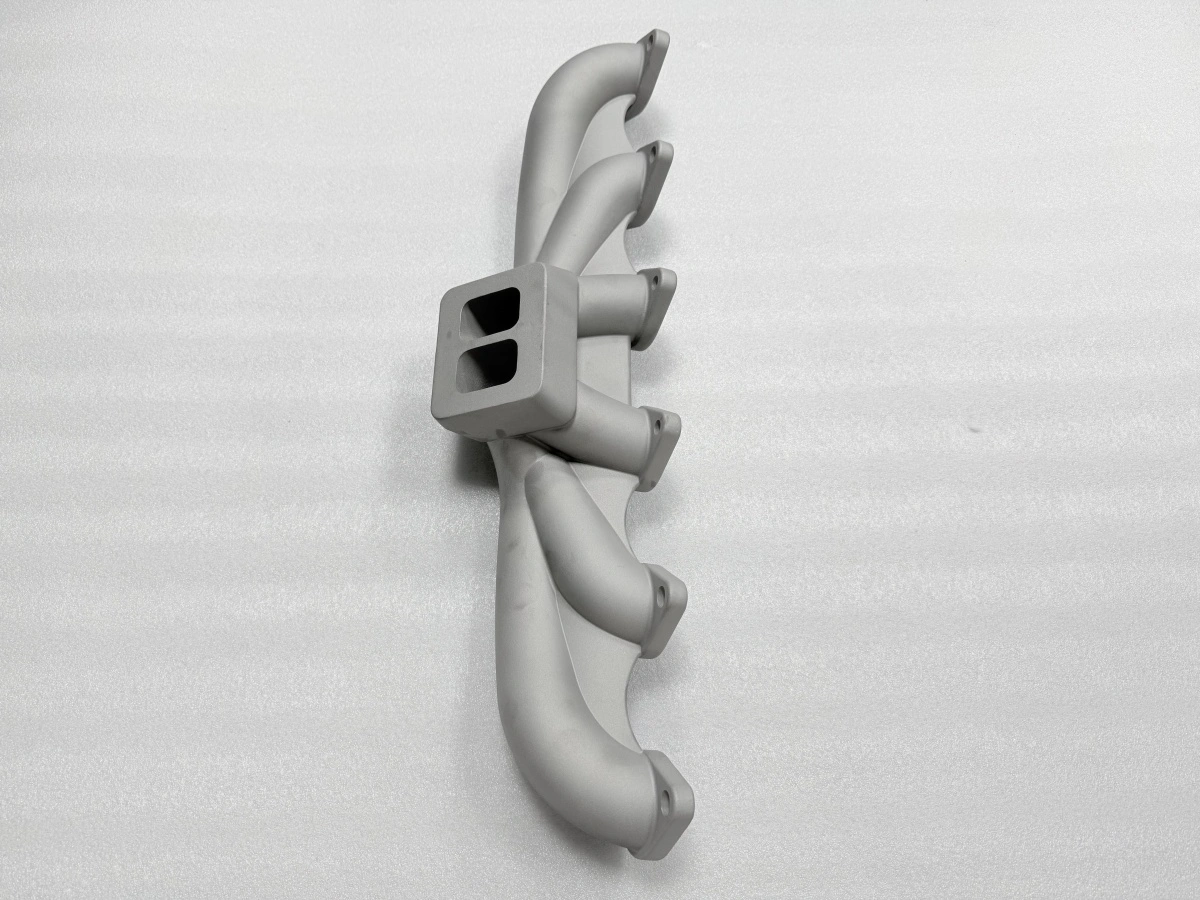
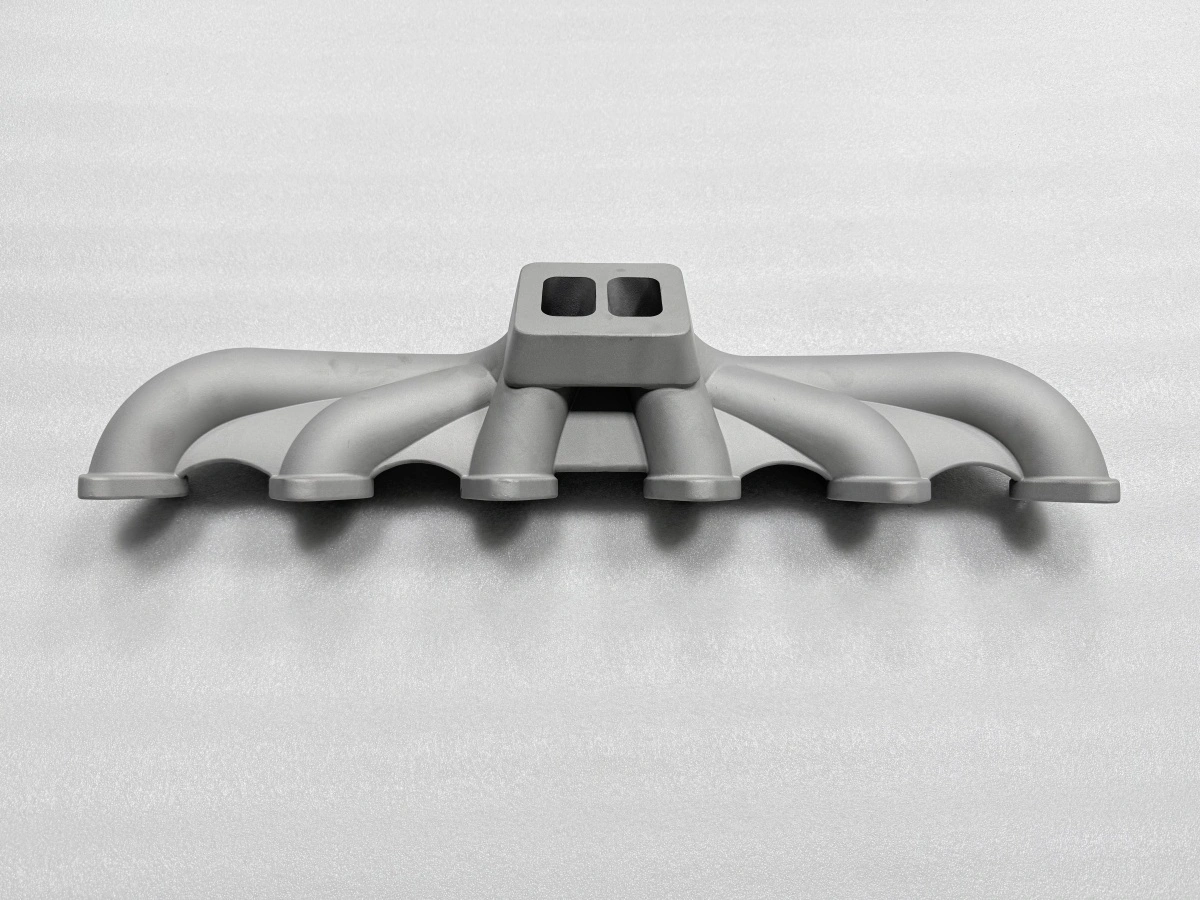
The record covers one part family and one route. It does not claim a universal fix. It shows which controls were changed, in what order, and what was measured before the part was released. The numbers below come from the case file; the mechanism is covered in a separate knowledge article and is only referenced here.
What did the cast manifold recovery case start from?
The starting point was a thin-wall stainless manifold with six runners and a two-port flange. The flange face had to hold flatness after machining. The casting route was chosen because the geometry was already a casting and the batch was small. The pattern was printed in wax, shelled, poured and cut.
The first article was measured on a coordinate measuring machine (CMM) before machining (case file). The flange face was outside the 0.05–0.10 mm acceptance band. Acceptance is 0.05–0.10 mm; the target is 0.05 mm. The bow was visible across the two-port flange, with the runner side sitting high. The part was not scrapped at that point; it became a decision about the next pattern.
Four values framed the work: shrinkage of 1.5–2.5%, a straightening allowance of 0.5–1.5 mm, stress relief at 850–950 °C, and the flatness band of 0.05–0.10 mm. Those values set the limits for every change that followed.
Where did the first pour warp?
The warp started at the flange, not at the runners. The thin runner wall froze first and became rigid. The flange boss stayed liquid longer and contracted later.
The shell held the runner side while the flange moved. The result was a bow across the flange face. The mechanism is covered in why cast manifolds warp.
Printed wax pattern: the pattern was scaled at the standard rate and shelled at five layers.
Pour and cut: the part was poured in the standard orientation and cut out after cooling.
First measurement: the flange face was outside the 0.05–0.10 mm band on the CMM.
Decision: the pattern was reprinted instead of straightening the first casting.
The gating was single-sided. The fed side stayed hot longer and contracted later. That added a twist to the bow. The first record did not separate the two effects, which is why the second pattern changed both the scale and the gating.
The shell schedule was also part of the failure. Five layers held the runner junction well enough to resist the flange contraction. The shell was a control that could move without changing the design.
What changed on the second pattern?
Four changes went into the second pattern. Each one targeted a different leg of the problem, and each one was recorded before the pour.
First, the wax pattern was scaled at 1.8%, inside the 1.5–2.5% range. The first pattern had used the low end of the range. The new scale gave the flange more room to contract before it was restrained by the shell.
Second, the gating changed from single-sided to symmetric. Two feeds replaced one. The fed side no longer stayed hot alone, so the twist component was reduced. The gating was still not a thermal design; it was a layout change that could be cut into the pattern.
Third, the shell went from five layers to seven. The extra layers stiffened the shell away from the runner junction and let the junction move. The first shell was checked before the pour.
Fourth, the dewax was slowed. A slower heat-up gave the shell time to dry and reduced the chance of a cracked shell at the runner junction. The schedule was written down so the next batch could repeat it. The pattern and shell changes were recorded separately; either alone would have been a guess.
Which controls held the wall?
The wall was held by three controls working together. The first was the shrink allowance. A 1.8% scale let the flange contract while the runner wall was still able to move.
The second was the gating layout. A symmetric feed kept both sides of the flange at a similar temperature, so the contraction was more even.
The third was the shell. Seven layers held the shell shape without clamping the runner junction. The shell was stiff where it needed to be and compliant where the part had to move. That split was the point of the change, and it was checked on the shell before the pour.
Stress relief came after the cut and before machining. The part was held at 850–950 °C, then cooled in the furnace. The flatness check was repeated after stress relief, because the measurement before and after can differ. The release decision used the post-stress-relief value, not the as-cut value.
The straightening allowance of 0.5–1.5 mm stayed on the drawing. It was not used to bend the part. It was there so that machining could clean the flange face without cutting into the wall. The allowance and the flatness band are separate numbers; the case used both.
How was the casting inspected?
Inspection was built around the flange face and the wall thickness. Four checks were recorded on the first part from the second pattern. The table lists what was measured and what released the part.
Check | What was measured | Criterion | Record |
|---|---|---|---|
Flatness | Flange face on CMM | 0.05–0.10 mm | Within band |
Wall thickness | Six runner walls | Drawing minimum | Within band |
Stress relief | Furnace cycle | 850–950 °C | Recorded |
Stock | Flange face allowance | 0.5–1.5 mm | Measured |
The CMM measurement was taken with the part supported at three points, not clamped. Clamping can flatten a bowed flange and hide the error. The support points were marked so the next part is measured the same way.
The wall thickness check used the same six points on every part. The points were chosen at the runner junction and at mid-runner. The record was a table of values. That table made the two patterns comparable.
What does this record prove?
It proves that this part family can be recovered by changing the pattern, the gating and the shell, and by measuring before machining. It does not prove that every warped casting can be saved. A part with a crack, a cold shut or a wall below the drawing minimum is not recovered by a new pattern.
The record also does not set an acceptance rule. The 0.05–0.10 mm band belongs to the drawing and the machining plan. The case shows the band being met on one part; it does not lower or raise it for another part.
The limit is the geometry. A compact part with a low length-to-thickness ratio may not need the same changes. A part free to shrink in every direction may pass without the scale change. If the bow appears only after machining, the pattern is not the place to look; check the fixture and the cut.
The working order for this band is: fix the shrink allowance, make the gating symmetric, stiffen the shell away from the junction, slow the dewax, then measure the first part on a CMM. If the route changes to printing, keep the measurement plan; the failure mode follows the geometry, not the process.
Share the print, the wall-thickness map and the flatness call-out with Neway. The team will advise which route fits: cast or printed, or an inter-operation stress relief. That review turns a one-off save into a repeatable plan.
FAQs