
Why Cast Manifolds Warp: Shrinkage, Constraint, Section
The reason why cast manifolds warp is that 1.5–2.5% shrinkage (ASM Handbook Vol. 7), flange constraint and section change act together. Molten stainless steel shrinks as it freezes, the flange and gating hold the part, and a thin wall freezes before the thick flange does. Residual stress bows the part after the shell is broken; flatness has a 0.05 mm target and a 0.05–0.10 mm acceptance band after stress relief at 850–950 °C (ISO 8062-3).
|
|
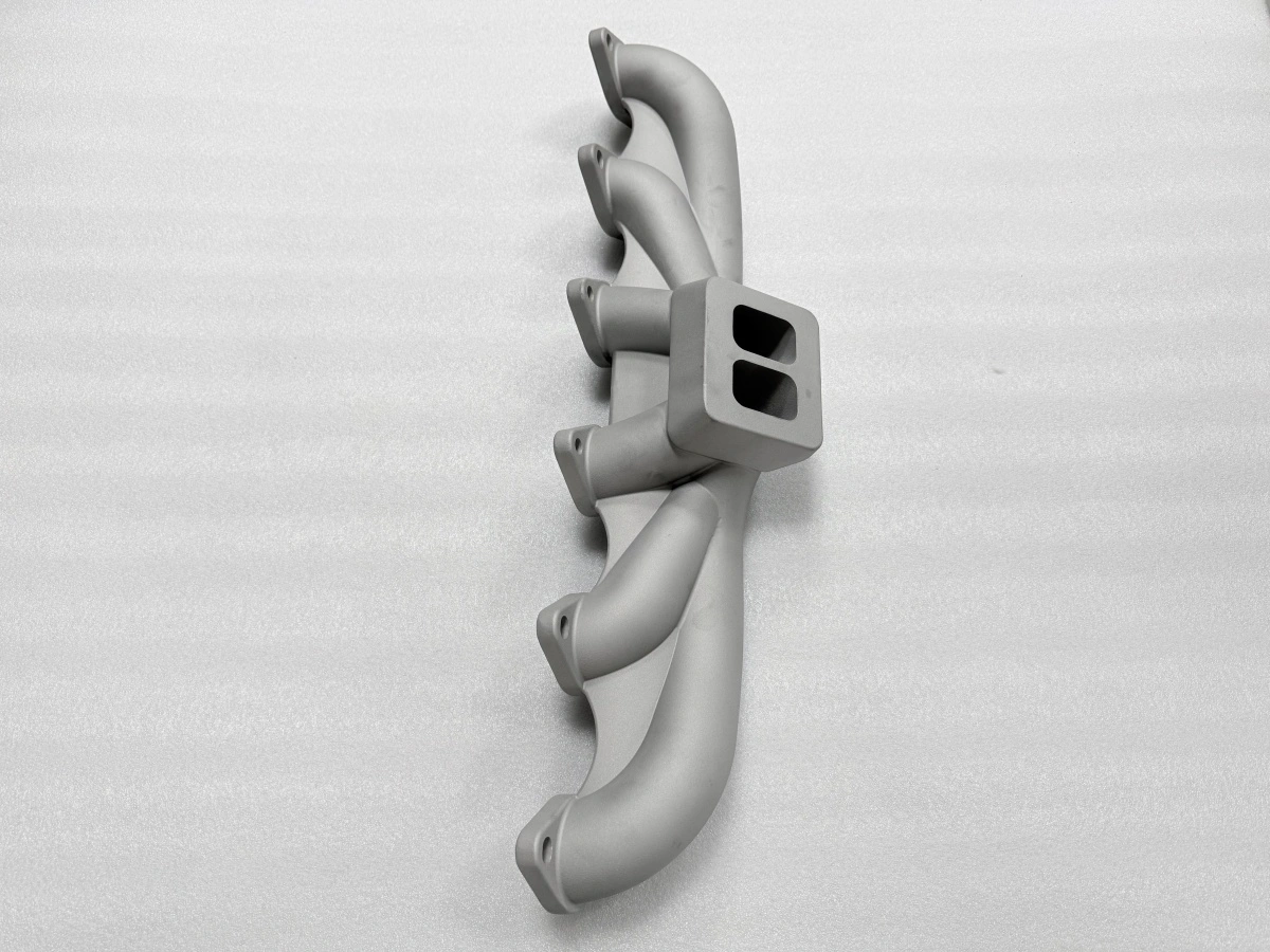
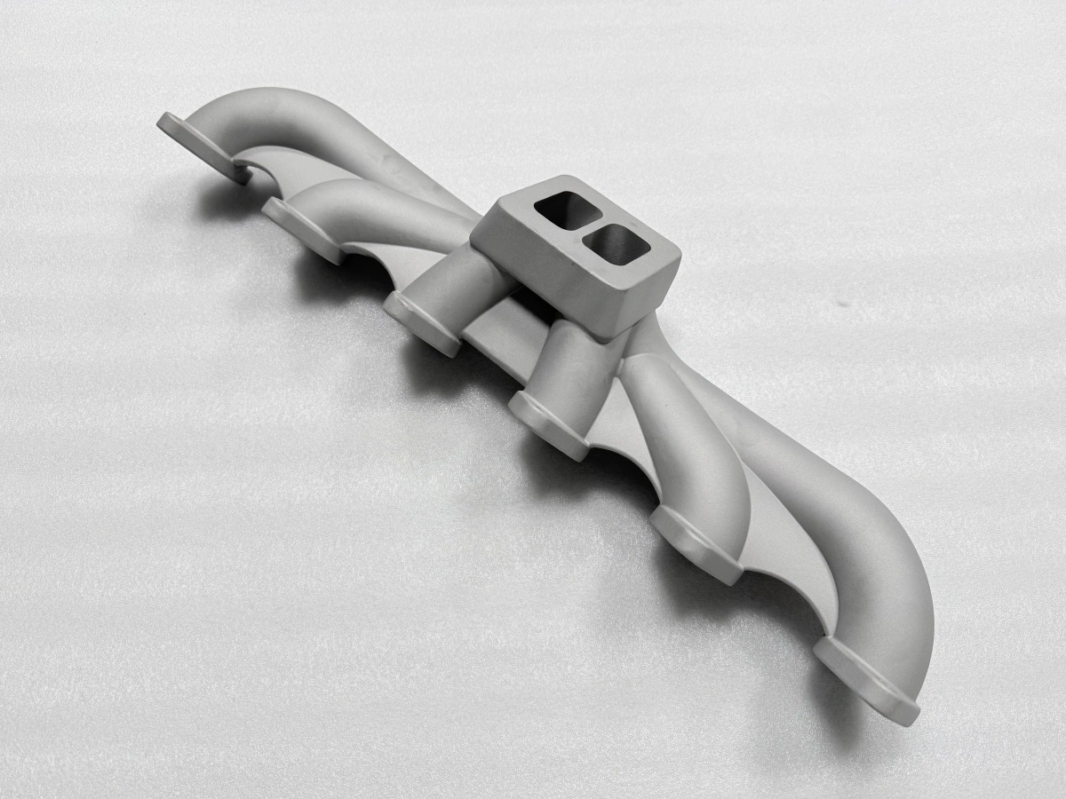
The mechanism is not a defect of one process. It is the same triangle in casting and in powder bed fusion (PBF). Only the levers change. That is why the controls below are written as pairs, and why a part that warps in one route usually has a twin failure mode in the other.
Why cast manifolds warp: where does it start?
It starts at the moment the first section freezes. A manifold has six runners and a flange, so it freezes in stages rather than as one block. The thin runner wall loses heat faster than the flange boss. It becomes rigid while the flange is still liquid and able to feed.
From that point the two sections contract at different times. The rigid runner resists the flange contraction. Stress builds at the junction. When the shell is broken the part is still hot and weak, so the stress bends it instead of cracking it.
The bow direction follows the last section to freeze. If the flange freezes last, it pulls the runners toward the flange face. If the runners freeze last, they pull the flange into a saddle. In both cases the visible error appears on the flange face, which is also the face that gets machined.
A second start point is gating. A single gate at one end feeds the part from one side. The fed side stays hot longer and contracts later.
The unfed end freezes first and holds the shape. The mismatch is a twist rather than a bow.
The freeze sequence is visible in the shell. A runner that freezes first shows a bright, smooth surface, while the flange beside it still shows a darker, hotter tone when the shell is broken. That difference is the gradient made visible.
Where does constraint come from?
Constraint comes from three places: the mold or shell, the gating system and the part's own geometry. The ceramic shell grips the pattern surface during dewax and holds the shell geometry while the metal freezes. A shell that is too strong at the runner junction acts like a clamp.
Gating adds constraint by feeding. A gate that stays liquid keeps feeding metal into the section that is shrinking, which reduces the stress locally. The same gate also holds the part at one point, so the free end moves. Both effects are real and they can cancel or add.
Geometry adds the strongest constraint. A flange is a closed ring with a high second moment of area, so it resists bending. A runner is an open tube with a low one. When the two are joined, the flange dictates the shape and the runner takes the strain.
Fixture and handling add the last part. A part that is straightened while hot keeps less stress than one that is left to cool unsupported. A part that is stacked before it is cool can take a set that looks like a warp but is actually handling damage.
Shell thickness adds constraint in a way that is easy to miss. A shell built to 8–10 mm at the runner junction is stiff enough to hold the runner while the flange moves, so the stress concentrates at the junction instead of spreading.
How does section change set the gradient?
Section change explains why cast manifolds warp at the flange rather than at the runner, and the gradient sets the stress. A 1 mm wall and a 12 mm flange boss in the same part cool at different rates. The thick section stores heat and freezes late; the thin one freezes early.
The casting shrinkage stress shows up first at the junction. The gradient scales with the thickness ratio, not with the absolute size. Doubling every wall in a manifold roughly doubles the freeze time but keeps the ratio, so the warp pattern stays similar. Changing one wall from 1 mm to 2 mm while the flange stays at 12 mm changes the ratio and the pattern.
The gate location decides which end of the gradient is fed. Feeding the thick flange keeps it liquid longer and increases the mismatch. Feeding the thin wall reduces the mismatch but risks a cold shut at the flange.
The gate's own freeze time is part of the gradient. A heavy gate stays liquid and feeds the section next to it, so that section cools later than the same section on the far side of the part.
Ribs and bosses are local section changes. A boss that is 6 mm thick on a 2 mm wall acts as a hot spot and a constraint at once. It freezes late and holds the wall, so the wall curls around it.
Which controls move the mechanism?
The manifold distortion mechanism is the same in both routes, and the controls act on one of the three legs. The table pairs them across routes.
A control that moves two legs at once is worth more than one that moves a single leg. Stress relief moves none of the three legs, but it removes the residual stress before machining, which is why it appears in both routes.
Control lever | Casting route | Additive route |
|---|---|---|
Shrinkage allowance | Pattern scaled 1.5–2.5% | Model scaled for melt and cool-down |
Constraint | Gating and shell strength | Orientation and support layout |
Section gradient | Wall and boss thickness | Build orientation and section change |
Stress relief | 850–950 °C before machining | Stress relief before separation |
Verification | Flatness 0.05–0.10 mm on CMM | Flatness 0.05–0.10 mm on CMM |
Shrinkage allowance is the cheapest lever to change and the easiest to get wrong. Scaling the pattern by 1.8% is only correct if the part is free to shrink. A constrained flange does not shrink by the same amount, so the first article is measured rather than trusted.
Gating and orientation are the levers that change the constraint. A symmetric gate layout gives the part a chance to contract evenly. A build orientation that puts the flange last keeps the stiff ring from locking the thin wall.
When does the mechanism not apply?
The mechanism assumes the part is thin-walled and restrained. A thick, compact part with a low length-to-thickness ratio stores less gradient and warps less. A part that is free to shrink in all directions relieves stress by shrinking rather than by bending.
It also assumes the alloy shrinks in a normal range. A change to a low-shrinkage alloy or a change to a different solidification path can move the numbers, though the triangle remains.
The mechanism does not explain why cast manifolds warp after machining. A part that is flat before machining and bowed after it is showing machining stress or fixture error, not casting shrinkage. The order of inspection matters more than the size of the bow.
The practical test is a before-and-after measurement. A part measured flat before machining and measured again after machining separates casting warp from machining movement in one step.
Finally, the mechanism does not set an acceptance limit. A 0.08 mm bow on a flange that will be faced is a stock question, not a rejection. The release decision belongs to the drawing and the machining allowance, not to the mechanism.
For a manifold that must hold 0.05–0.10 mm flatness after machining, the practical route is to fix the gradient and the gating before the first pour, then measure the first article on a coordinate measuring machine (CMM). If the same part is moving to a printed route, keep the same measurement plan; the failure mode does not change with the process.
Send the drawing, the wall map and the flatness requirement to Neway, and the team will confirm whether the part should be cast or printed, or stress-relieved between operations. That review is where a warping risk becomes a controlled plan rather than a first-article surprise.
FAQs