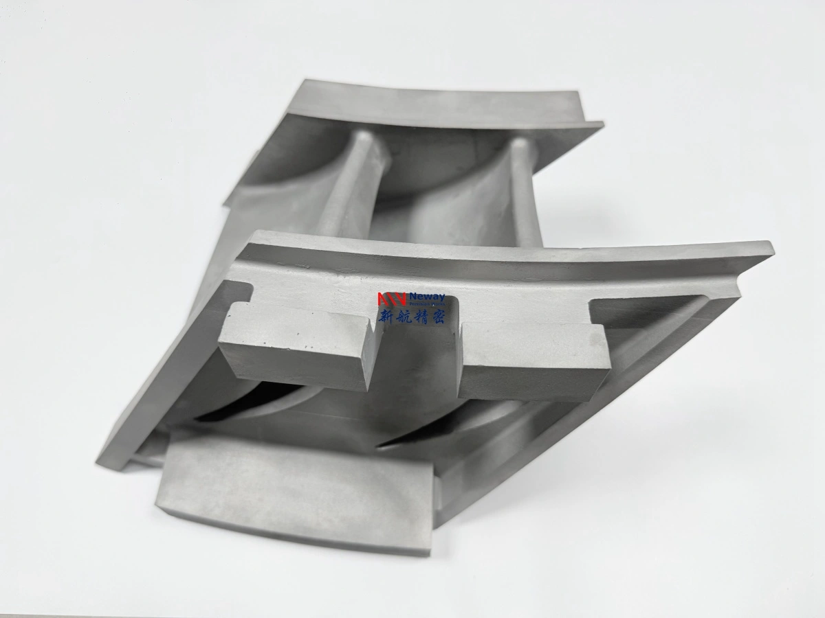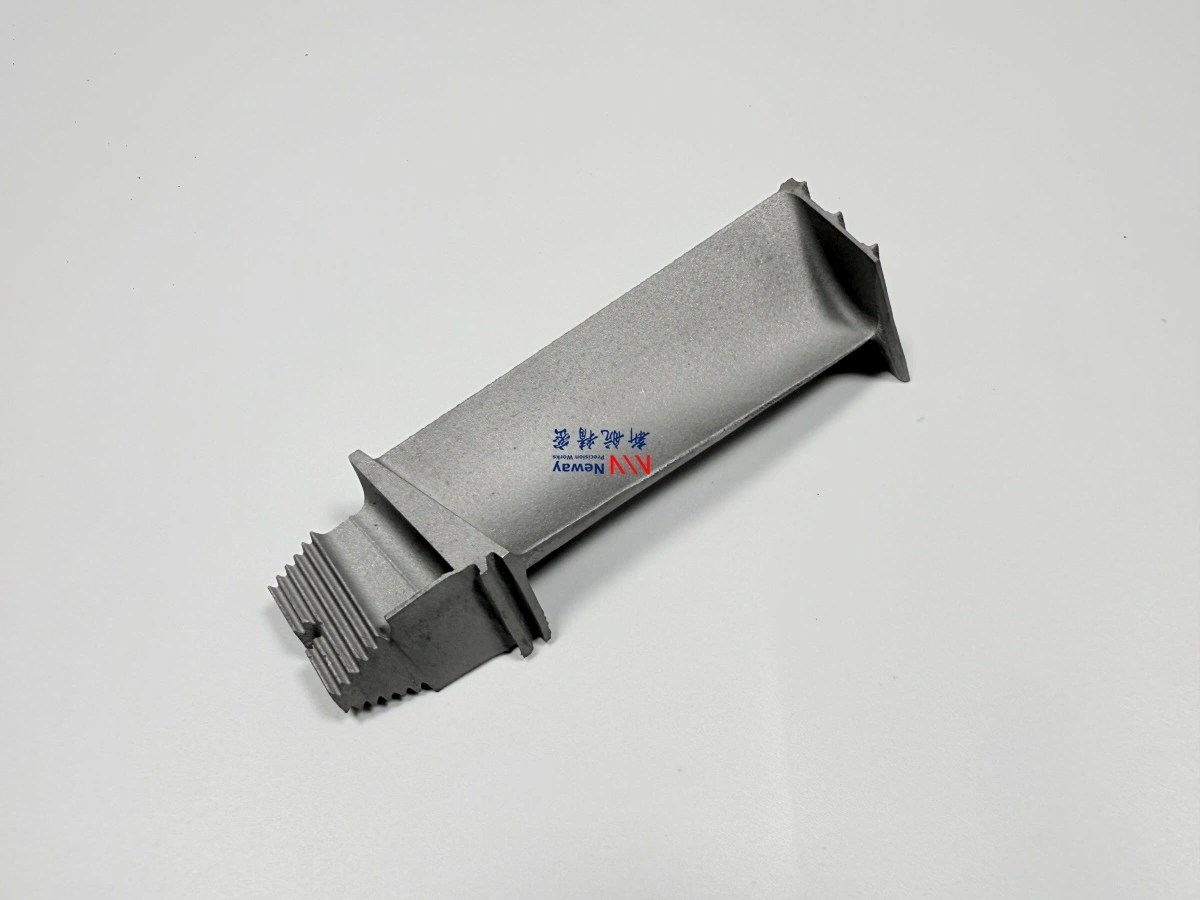
3D Printed Wax Pattern Process: Print to Vacuum Casting
Printing removes the tooling step that casting needs, and nothing else. It keeps the same ceramic shell, dewax, burnout and vacuum pour, so a foundry can adopt it without new equipment. The only new decisions are the resin, the pattern's thermal expansion and print orientation. Here the 3D printed wax pattern process is treated as a foundry route, not a printing job: a printed wax to vacuum casting workflow for the investment casting workflow check.
|
|
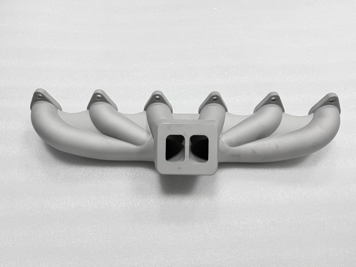
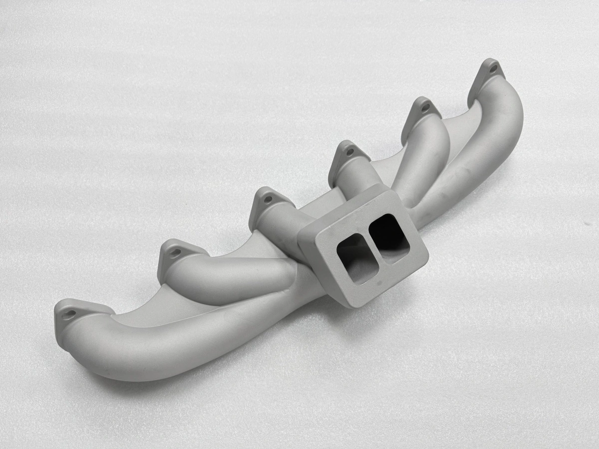
The pattern is printed instead of injected, and that single change carries the commercial case. A manifold that needs two or three pieces does not justify a machined mold, while a part that will run for years is cheaper per piece from a mold than from any printed pattern. The commercial case sits with cast stainless manifolds in low-volume work, where the printed route pays for itself.
Casting knowledge still decides the outcome. Gating, shell schedule, dewax ramp and pour temperature are foundry decisions that a printed pattern does not change, and a printer that ignores them will fail in the same places as an injection shop. That is why this page follows the pattern through the foundry rather than stopping at the print.
What changes in the 3D printed wax pattern process?
Four things change, and each one has a process consequence. The resin burns out differently from wax, the printed part is more brittle during handling, the pattern's thermal expansion is lower, and the surface finish depends on layer height rather than on a polished mold.
The expansion change matters most for the shell. A printed pattern expands less before it melts, so the shell sees a different pressure profile during dewax and may need a slower ramp than the schedule written for injected wax. The finish change matters for inspection, because layer lines can mask a small surface defect.
The brittleness change matters on the bench. Printed patterns chip at thin edges and at the runner attachments, so the tree design has to avoid sharp transitions that an injected pattern would survive. A chip that goes unnoticed becomes a shell inclusion that shows up after the pour.
Print orientation decides where the layer lines land. A pattern printed with its flange face flat shows layer steps on the gasket surface, while the same part printed at an angle pushes those steps onto a non-critical face; the orientation is a drawing decision, not a printer setting.
Repeatability is the fourth gain and the one that pays across a batch. A printed pattern is identical from print to print, so the tenth casting matches the first within the CT5–CT7 band once the compensation is set, while an injected pattern drifts with mold wear.
Which steps remain unchanged when the pattern is printed?
The steps that follow the pattern are the same four that any investment casting uses. Only the pattern-making step is replaced, which is why the route can be quoted without rebuilding the foundry around it.
Treeing: attach the printed pattern to a wax runner and a pouring cup, with gates sized for the metal flow rather than for handling convenience.
Shelling: dip and stucco to 5–8 coats for a 6–10 mm shell; the count follows part size and wall thickness.
Dewax and burnout: hold the heat-up under 2 °C per minute, then fire at 800–1100 °C for 1–2 h to clear the residue.
Pour, knock-out and stress relief: cast at 1550–1650 °C, break the shell after the metal loses color, and relieve stress before computer numerical control (CNC) machining services.
The shell schedule is the one place where the printed pattern changes a number. A printed pattern usually needs one more coat than an injected pattern of the same geometry, because the pattern surface is rougher and the shell keys to it differently.
Dewax is where a printed pattern differs most from an injected one. The printed resin softens over a narrow range and expands slightly before it flows, so the first part of the ramp is slower than the wax schedule and the hold at the top is longer; a shell that is dry but not fully cured will crack at this stage even when the pattern is good.
Where does the printed pattern route lose time?
The 3D printed wax pattern process loses time in four places, and printing is the first. Printing is on the critical path in a way that injection is not. A manifold-sized pattern set can take a day or more on a resin printer, and batching several parts onto one build plate only helps when they share a resin and a layer height.
The shell build is the second loss. Each coat has to dry, so a 6–8 coat shell can take several days in a humid season, and the drying record is the only way to tell later whether a dewax crack came from the schedule, the weather or the pattern.
The correction loop is the third loss. The first article is measured, and if the shrinkage compensation was wrong the pattern is reprinted and the shell rebuilt, which costs one to two weeks. Settling the compensation convention during the request-for-quotation (RFQ) review is cheaper than settling it after the first pour.
Coordination is the fourth loss. The printer, the shell shop and the foundry are often three companies, and each handover adds a day plus a chance to lose the compensation convention. One owner for the chain loses less time than three owners who each optimize their own step.
Season matters more than most schedules admit. A shell built in a dry week can lose a day to a humid one, and the correction loop inherits that variance; keeping the drying record per shell lets the next batch plan around the season instead of blaming the pattern.
Which shell parameters decide success?
Four parameters decide whether the shell survives the pour, and they interact rather than simply add up. The table below gives the schedule used for a 300 mm stainless manifold with a 1.0 mm wall; the thickness column is the target after each pair of coats.
Coats | Target thickness (mm) | Function |
|---|---|---|
1–2 | 1.5–2.0 | Surface detail and pattern keying |
3–5 | 4.0–6.0 | Strength at runner junctions |
6–8 | 8.0–10.0 | Pour pressure and thermal shock |
The slurry and stucco control the surface and the strength, and the drying conditions control how each coat sets. The dewax ramp is the fourth parameter: a ramp that is safe for a 3 mm wall will crack a 1 mm wall, which is why the ramp is written per part rather than per shop.
The primary coat is the one that touches the pattern, so its viscosity is checked before the first dip rather than after a defect appears. A slurry that is too thick bridges the layer lines and hides them under the shell, which makes the casting look smoother than the pattern was.
How is the pour controlled on a printed pattern?
The pour temperature is set by alloy and section, not by the pattern. Stainless runs at 1550–1650 °C (ASM International Handbook Vol. 7), and a thin wall needs the upper half of that band to fill before the metal freezes.
Vacuum or inert gas is set by the alloy's sensitivity. Stainless benefits from vacuum or argon, and the pressure holds metal in the cavity while the shell is still hot; losing vacuum at the wrong moment shows up as a short fill at the end of the longest runner.
The fill rate is set by the gating, and the gating is set by the tree. A single gate at one end of a manifold fills unevenly, and the last section to fill is the last to freeze, so a symmetric or stepped gate layout is the cheapest way to reduce the thermal gradient before anything is printed.
Shell preheat is the last variable before the metal lands. A cold shell chills the first metal into the cavity and can produce a lap at the gate, while an over-hot shell weakens under the pour's weight, so the preheat is set with the alloy and recorded with the pour.
Cooling after the pour is part of the same control. The casting cools inside the shell and the shell is broken only after the metal loses its color, because stripping early produces a bow that appears in machining rather than in inspection.
What is checked before the casting is released?
The inspection gate checks surface, dimensions and soundness before the part goes to machining. Cold shuts, trapped sand and visible cracks reject the casting, while a rough skin is only a stock question.
Dimensional checks run against CT5–CT7 (ISO 8062-3), and the drawing has to separate as-cast sizes from machined sizes. Checking an as-cast size against a machined tolerance is how a good casting is rejected for a reason that belongs to the next operation.
Machining stock is checked at the same inspection gate. The flange face needs a 0.8 mm target stock, accepted across a 0.5–1.5 mm band, so that the as-cast bow can be removed and the face still finished; a flange that runs 0.2 mm under on one side has nothing left to cut.
The measurement method decides what the inspection gate can see. A coordinate measuring machine (CMM) scan of the flange face shows the direction of the bow, while a single caliper reading across the flange cannot tell a bow from a twist; the record should name the method next to the number.
Traceability closes the record. The heat number, lot and part number written on the release sheet are how the same casting is found again months later, when a machining problem shows up; a sheet missing them releases a part nobody can trace back.
The release record closes the loop with the shell and pattern records. A casting that passes inspection but cannot be tied to a shell lot and a pattern revision is a sample rather than a production part, and the next batch has to start from measurement again.
For the 3D printed wax pattern process, the wrong choice is a straight tube with two flanges and a batch of a handful of pieces, because a weldment or a machined mold is cheaper at that size. A release is not proof of customer approval, bench performance or material certification, and it should not be read as one.
Share the model and the batch quantity with Neway, and we will confirm the route, the shell plan and the inspection gate before the first tree goes up. That confirmation is where the next step becomes a quote rather than a guess.
FAQs
.webp)