
Precision Metal Additive Manufacturing: Tolerance Risk Guide
Precision metal additive manufacturing should be quoted from the dimensions that control function, not from the assumption that every feature will hold a tight tolerance straight from the printer. A printed metal blank can be a good route for complex geometry, but bearing seats, threads, flat sealing faces, datum pads, and positional interfaces often need CNC, EDM, or a defined inspection stage.
This tolerance review is for buyers sending custom metal 3D printed parts where the finished part must assemble, seal, rotate, locate, or pass CMM inspection. The risk is not only build accuracy. Build orientation, support distortion, heat-treatment movement, HIP movement, machining allowance, datum strategy, and inspection access can all change the delivered tolerance boundary.
Neway reviews precision RFQs by separating as-printed features from finished features. If the drawing does not identify critical-to-function dimensions, the quote can understate machining, EDM, inspection, or rework risk. A clear drawing helps decide which dimensions can remain printed and which must be finished after post-processing.
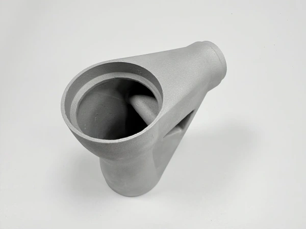
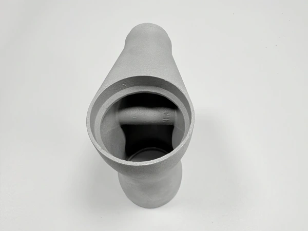
As-Printed Accuracy Is Not Finished Tolerance
Powder-bed metal printing creates a near-net part. It does not automatically create a finished precision component. As-printed surfaces are affected by layer direction, thermal history, support contact, powder removal, surface texture, and local feature size. A buyer should expect different control levels for external walls, internal passages, holes, flat faces, and machined interfaces.
Finished tolerance belongs to the complete manufacturing route. A hole may be printed undersize and then bored or reamed. A thread may be printed as a pilot feature and then tapped or thread milled. A sealing face may be printed with stock and then milled after stress relief or HIP. A datum may need a designed pad that survives support removal and remains accessible to the machine tool.
Critical-to-function dimensions should be marked on the 2D drawing. If every dimension is given the same tolerance, the supplier may have to quote unnecessary finishing. If no dimension is marked as critical, the supplier may assume that as-printed features are acceptable where the buyer expects machined accuracy.
Feature type | As-printed risk | Finished route usually reviewed | Inspection evidence to define |
|---|---|---|---|
Datum pads and locating faces | Support scars, heat movement, and surface waviness can shift the reference. | Print with machining stock, stress relieve, then machine datum surfaces. | CMM datum setup and drawing-based report. |
Bores, bearing seats, and bushings | Roundness, position, and surface finish may not meet assembly needs. | CNC boring, reaming, or EDM depending on material and access. | Diameter, position, roundness, and gauge requirement. |
Threads | Small printed threads can trap powder or lose profile definition. | Printed pilot hole plus tapping, thread milling, or insert review. | Thread gauge, depth, and engagement length. |
Internal channels | Ordinary CMM cannot see hidden geometry or trapped powder. | Design for powder removal and consider CT or flow-related acceptance. | CT, sectioning, leak test, or buyer-defined functional test. |
Build Orientation Creates Dimensional Bias
Build orientation affects support layout, thermal gradients, surface direction, feature stair-stepping, and machining access. A vertical hole, horizontal bore, overhanging pocket, and thin wall do not carry the same tolerance risk. Orientation can also decide whether a sealing face is supported, exposed, or positioned for machining stock.
Support distortion is a common source of tolerance surprise. Supports hold the part during printing but can leave witness marks and local stress after removal. A support-heavy face should not be used as a finished datum unless it will be machined later. If a critical surface cannot tolerate support marks, that requirement should be stated before orientation is selected.
Large flat areas can move during printing or post-processing. Thin walls can relax after the build plate is removed. Tall slender features can shift when support is cut away. If a buyer needs flatness, perpendicularity, position tolerance, or profile tolerance, the drawing should identify whether the requirement applies before or after heat treatment and machining.
For powder bed fusion, orientation is not only a production decision. It is part of the tolerance plan. When the buyer sends a drawing with GD&T, Neway can review whether datum surfaces, inspection access, and finishing stock support the tolerance scheme.
Post-Processing Can Move the Part Before Final Measurement
Stress relief, heat treatment, and HIP can change residual stress and dimensional condition. They may be needed for material performance, density-related acceptance, fatigue-sensitive applications, or buyer specifications. They also affect when final CNC or EDM should be performed.
Final precision machining is usually reviewed after stress-relief or HIP steps that can move the part. If finishing is done too early, later thermal processing may shift the machined surfaces. Rough machining before thermal processing can be useful when stock is heavy, but final datums, sealing faces, and high-accuracy bores should be timed around the required post-processing route.
HIP dimensional movement should not be treated as a fixed number unless the geometry, material, and acceptance requirements are known. A thin bracket, thick manifold, and dense tooling insert can respond differently. The quote should state whether HIP is required by the drawing, optional for risk reduction, or not needed for the application.
Machining Allowance Must Protect Datums and Access
Precision AM parts often need machining allowance, but allowance must be placed where a tool can actually reach. A hidden bore, deep internal feature, or pocket behind a rib may not be accessible after printing. A buyer should not assign CNC-level tolerances to surfaces that cannot be reached by a milling cutter, boring tool, grinding wheel, or EDM electrode.
CNC machining is commonly used for datum pads, bolt faces, bores, slots, sealing faces, and thread preparation. EDM machining may be reviewed for hard materials, narrow slots, delicate features, sharp internal corners, or precision profiles where conventional cutting access is limited.
Machining tabs and sacrificial pads can help. They provide clamping, datum setup, or inspection references without forcing the final part geometry to carry the manufacturing load. These features should be discussed before the order if they must be removed later.
Tolerance requirement | Risk if left as printed | Finishing path to quote | Buyer note before PO |
|---|---|---|---|
Flatness on mounting face | Thermal movement, support marks, and surface waviness. | Machine after thermal steps and define datum sequence. | State mating part and gasket or bolted condition. |
Position tolerance on hole pattern | Printed holes may drift with orientation and support removal. | Print pilot holes, machine or ream from finished datum. | Identify primary datum and assembly requirement. |
Profile tolerance on contoured surface | Layer texture and local shrinkage can affect surface envelope. | Review machining, EDM, polishing, or inspection-only acceptance. | Clarify whether the contour is functional or aerodynamic/cosmetic. |
Internal channel location | CMM cannot directly verify hidden geometry. | Design for CT, sectioning, flow test, or process control evidence. | Define which evidence is acceptable for hidden features. |
CMM and CT Serve Different Acceptance Questions
CMM is useful for accessible external dimensions, datums, hole patterns, flatness, and machined interfaces. It cannot fully inspect closed internal channels, trapped powder, or hidden lattice features. CT or X-ray methods may be reviewed when internal geometry, porosity screening, or powder removal evidence is part of acceptance.
The buyer should decide which inspection record is needed before the quote is finalized. A basic dimensional check, full CMM report, first-article inspection, CT scan, surface finish record, material certificate, or heat treatment record can each change price and lead time. Inspection should match the failure mode, not simply be added as a generic note.
For precision metal additive manufacturing, testing equipment selection should follow the drawing. Position tolerances need datum setup. Internal cooling channels may need CT or a functional test. Sealing faces may need surface finish and flatness evidence. Threads may need gauge confirmation.
Drawing Notes That Prevent Tolerance Disputes
Before PO release, send the STEP file, 2D drawing, material grade, intended process, quantity, application environment, critical-to-function dimensions, GD&T datum scheme, machined surfaces, post-processing expectations, surface finish, and inspection records required for acceptance. Mark which dimensions apply to the finished part and which features may remain as printed.
If the part has internal geometry, state whether CT, sectioning, pressure test, flow check, or visual access is required. If the part has fatigue-sensitive surfaces, sealing interfaces, bearing seats, or assembly datums, specify the finishing route or ask Neway to quote alternatives. A precision quote is stronger when the buyer separates printed geometry, finished geometry, and inspection evidence at the start.
For background on accuracy expectations in metal AM, buyers can also review Neway's article on precision custom metal parts with tight accuracy. The quotation should still be based on the current drawing, not a general process claim.
Related FAQs
.webp)
.webp)
