What Tolerances Can AlSi10Mg 3D Printed Parts Achieve After CNC Machining?
What Tolerances Can AlSi10Mg 3D Printed Parts Achieve After CNC Machining?
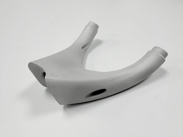
AlSi10Mg 3D printing is suitable for producing complex aluminum structures, but critical dimensions usually require CNC machining after printing. In general, the printed blank is used to create the complex geometry, while CNC machining is used to control holes, threads, sealing surfaces, datum faces, bearing seats, and other precision features.
1. Direct Answer: Printed Blank vs CNC-Machined Features
As-printed AlSi10Mg parts are suitable for general structural dimensions, lightweight features, and complex geometry. However, when the part requires tight tolerance, accurate hole position, smooth sealing contact, or reliable assembly fit, CNC post-machining should be specified in the RFQ.
Feature Type | Recommended Manufacturing Method | Reason |
|---|---|---|
Complex external or internal structure | 3D printing | Best for lightweight geometry, integrated features, and complex shapes |
Critical holes and bores | CNC machining | Improves diameter, roundness, and position accuracy |
Threads | CNC machining or tapping | Printed threads are usually not recommended for precision assembly |
Sealing faces | CNC machining, grinding, or polishing | Improves flatness and surface roughness for sealing performance |
Assembly or datum surfaces | CNC machining | Controls flatness, parallelism, perpendicularity, and datum references |
2. Which Features Need CNC Machining?
CNC machining should be applied to any feature that affects fit, sealing, alignment, or repeatable assembly. For precision AlSi10Mg printed parts, the following features are commonly machined after printing:
Mounting holes and precision bores
Threaded holes and tapped features
Sealing surfaces and gasket contact faces
Assembly faces and datum planes
Locating pins, slots, and positioning surfaces
Bearing seats, shaft interfaces, and press-fit areas
This hybrid route is common for manufacturing and tooling applications where the part needs both complex geometry and reliable dimensional accuracy.
3. Design Allowance for CNC-Machined AlSi10Mg Printed Parts
When AlSi10Mg parts are designed for printing plus CNC machining, machining allowance should be added to critical surfaces. This prevents the final part from depending directly on the as-printed surface for functional accuracy.
Add machining stock to sealing faces, datum faces, and assembly surfaces
Print pilot holes smaller than the final hole size, then machine to final tolerance
Avoid placing tight tolerances on rough as-printed surfaces unless finishing is planned
Clearly mark all machined surfaces on the 2D drawing
Confirm fixture access before finalizing the design
The correct allowance depends on part size, geometry, orientation, and machining access, so it should be reviewed together with the 3D model and 2D drawing.
4. Role of Powder Bed Fusion in Precision AlSi10Mg Parts
Powder bed fusion is responsible for producing the near-net-shape aluminum part. It enables complex lightweight structures, internal features, and optimized geometries that would be difficult or expensive to machine from billet.
Printing creates the complex aluminum blank
CNC machining finishes critical functional areas
Inspection verifies final dimensions after post-processing
This combination is often the most practical route for custom AlSi10Mg components that require both design freedom and precision.
5. Inspection for CNC-Machined AlSi10Mg Printed Parts
Inspection should be selected based on the drawing requirements and final application. For precision AlSi10Mg printed parts, dimensional verification is usually performed after CNC machining.
Inspection Method | Typical Purpose |
|---|---|
CMM inspection | Checks critical dimensions, GD&T, datum relationships, and hole positions |
3D scanning | Compares full-surface geometry against CAD data |
FAI report | Documents first article dimensional conformity for engineering approval |
Surface roughness testing | Verifies sealing faces, contact surfaces, or cosmetic requirements |
6. Quote Requirements for Tolerance-Controlled Parts
To quote AlSi10Mg 3D printing with CNC machining accurately, the supplier needs a 3D model and a 2D drawing. The drawing should clearly identify which dimensions are critical and which surfaces require machining.
3D CAD file for geometry and printability review
2D drawing with tolerances and GD&T requirements
Thread specifications, hole sizes, and fit requirements
Surface roughness requirements for sealing or contact faces
Quantity and inspection requirements
Final application environment and assembly function
7. Summary
AlSi10Mg 3D printed parts can achieve practical engineering accuracy when printing and CNC machining are combined correctly. Printing is used to produce the lightweight and complex aluminum structure, while CNC machining controls critical dimensions, holes, threads, sealing faces, and assembly surfaces. For tolerance-controlled AlSi10Mg parts, the 2D drawing should clearly define all critical features, machining surfaces, and inspection requirements.
If you need AlSi10Mg 3D printing with CNC machining, provide the 3D CAD file, 2D drawing, quantity, tolerances, surface requirements, and inspection needs so the manufacturing route and quotation can be evaluated accurately.