How Powder Bed Fusion Prints TA15 Titanium Alloy Parts
How Powder Bed Fusion Prints TA15 Titanium Alloy Parts
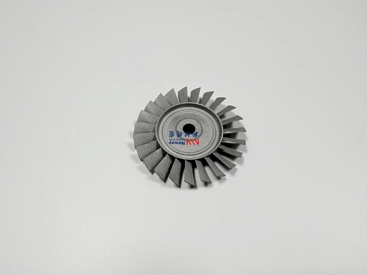
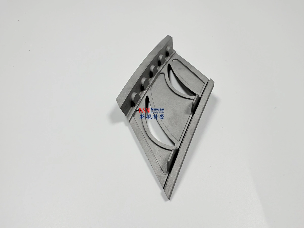
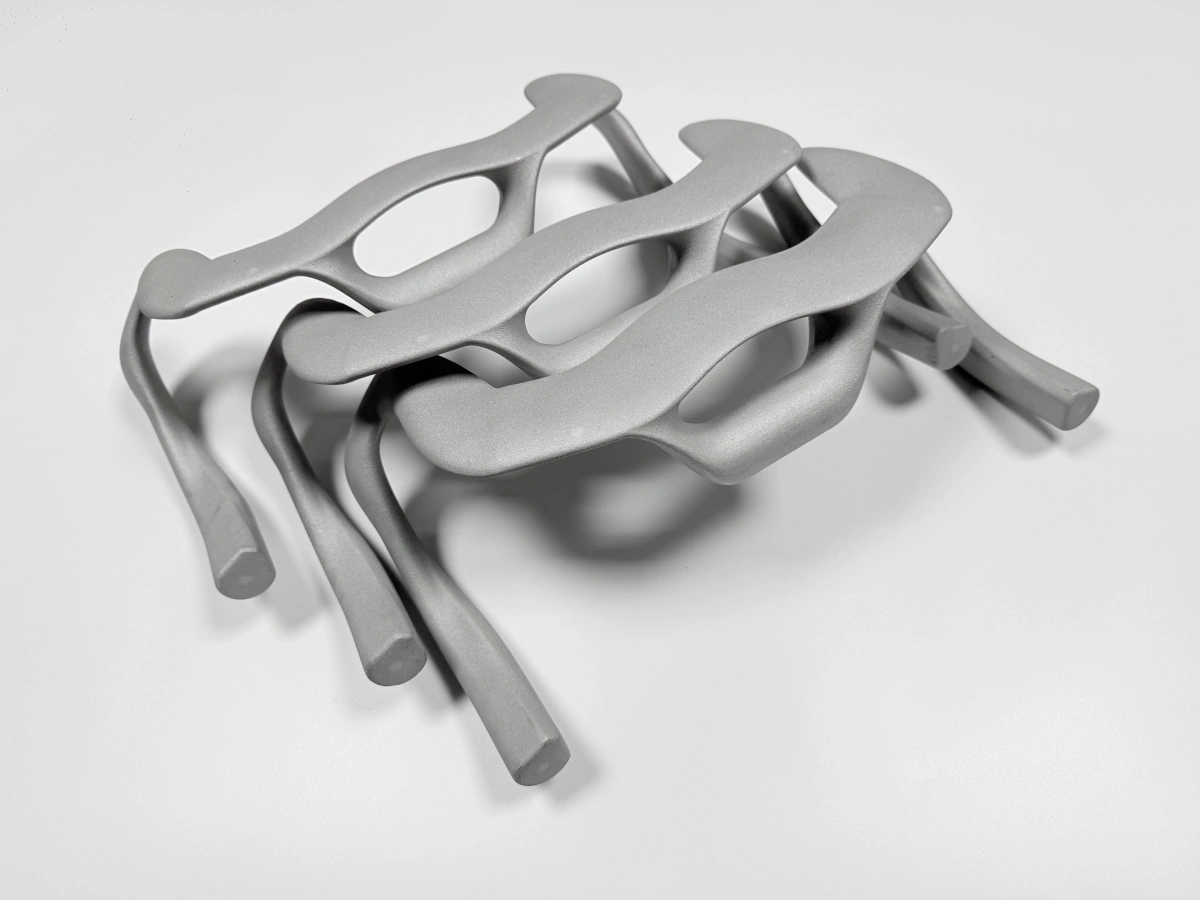
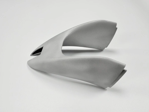
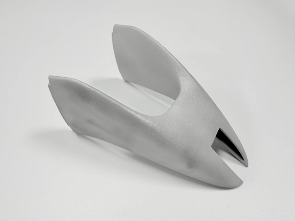
TA15 powder bed fusion is used to manufacture high-strength titanium alloy parts with complex geometry, lightweight structure, and aerospace-oriented performance requirements. Compared with conventional machining from titanium billet, powder bed fusion can build near-net-shape TA15 parts directly from CAD data, making it suitable for integrated brackets, load-bearing structures, lightweight connectors, complex housings, and aerospace validation components.
At Neway3DP, our TA15 Titanium 3D Printing Service supports custom titanium alloy parts for engineering prototypes, aerospace structural parts, and low-volume production. We combine powder bed fusion process planning, build orientation review, support design, heat treatment, CNC post-machining, surface treatment, and inspection to help customers produce functional TA15 titanium components.
For engineers and technical buyers, the value of TA15 additive manufacturing is not only in printing a titanium shape. The process must control thermal stress, oxygen exposure, deformation risk, support removal, final machining allowance, and inspection requirements so the printed part can meet real assembly and application needs.
Why TA15 Requires Controlled Printing
TA15 titanium alloy parts require controlled printing because titanium alloys are sensitive to heat input, oxygen exposure, residual stress, and deformation during laser powder bed fusion. During SLM printing, the powder is rapidly melted and solidified layer by layer. This repeated thermal cycle can create internal stress, especially in thin-wall structures, large flat areas, overhangs, and load-bearing aerospace components.
For TA15 aerospace parts, uncontrolled stress or poor build planning can lead to distortion, support removal difficulty, dimensional drift, or surface quality issues. This is why TA15 SLM printing should be planned with engineering review before production, including material confirmation, build orientation, support strategy, stress relief, and post-machining allowance.
Control Factor | Why It Matters for TA15 Printing | Engineering Focus |
|---|---|---|
Thermal stress | Rapid heating and cooling can create residual stress and distortion | Build orientation, support strategy, stress relief, heat treatment |
Oxygen control | Titanium alloys are reactive at high temperature and require controlled atmosphere | Powder quality, chamber atmosphere, process consistency |
Deformation control | Thin walls, large sections, and uneven structures may move during printing or removal | Support layout, heat treatment route, machining allowance |
Surface quality | Supported surfaces and down-facing areas may need additional finishing | Orientation planning, support contact area, surface treatment |
Final tolerance | As-printed dimensions may not meet precision assembly requirements | CNC machining, datum planning, inspection strategy |
Powder Bed Fusion Process for TA15 Titanium Parts
Powder Bed Fusion is suitable for TA15 titanium alloy parts because it can manufacture dense metal components with complex shapes, integrated structures, and lightweight features. In the process, a thin layer of TA15 titanium alloy powder is spread across the build platform, and a laser selectively melts the powder according to the sliced CAD model.
The process repeats layer by layer until the full TA15 part is formed. This makes powder bed fusion valuable for aerospace structures where complex geometry, part consolidation, and weight reduction are important. However, final part quality depends on powder quality, laser parameters, build layout, support strategy, atmosphere control, and post-processing.
Process Step | Purpose | Engineering Focus |
|---|---|---|
CAD and drawing review | Evaluate printability and final application requirements | Wall thickness, internal channels, tolerance zones, datum surfaces, inspection notes |
Build preparation | Prepare slicing, orientation, support layout, and machining allowance | Support reduction, deformation control, surface quality, powder removal |
Laser melting | Melt TA15 powder layer by layer into a dense titanium structure | Laser parameters, scan strategy, oxygen control, powder consistency |
Support removal | Remove supports and separate the part from the build plate | Protect thin walls, functional surfaces, and aerospace structural features |
Final processing | Improve dimensional accuracy, surface condition, and mechanical stability | Heat treatment, CNC machining, surface treatment, inspection |
Build Orientation for TA15 SLM Printing
Build orientation is a major factor in TA15 SLM printing because it affects support volume, deformation risk, surface finish, build height, machining allowance, and total cost. A different orientation can change how the part is supported, where the support marks appear, and whether critical surfaces can be finished efficiently after printing.
For TA15 aerospace parts, build orientation should be selected based on both additive manufacturing feasibility and final assembly requirements. Critical holes, mounting faces, datum surfaces, sealing faces, and load-transfer interfaces should be reviewed before printing so machining allowance and inspection strategy can be planned correctly.
Build Orientation Factor | Impact on TA15 Printing | Planning Method |
|---|---|---|
Support structure | More supports increase material use, removal labor, and surface finishing | Reduce supports on functional and visible surfaces where possible |
Build height | Higher build height can increase printing time and cost | Balance build height with support reduction and deformation control |
Deformation risk | TA15 structural parts may distort if stress is not controlled | Use suitable orientation, support design, and heat treatment route |
Surface quality | Down-facing and supported surfaces usually require more finishing | Place critical surfaces where post-processing can be controlled |
Machining allowance | Functional features need extra stock for CNC finishing | Plan allowance for holes, threads, datums, and mating faces before printing |
Support Removal for Complex TA15 Aerospace Structures
Support removal is an important part of the TA15 titanium alloy 3D printing process. Supports are necessary during printing to anchor the part, manage heat, and stabilize overhangs, but they must be removed carefully after printing. For complex aerospace structures, support removal can affect surface quality, dimensional accuracy, and downstream machining work.
A good support strategy should protect critical surfaces and avoid placing heavy supports on areas that are difficult to access or finish. For thin walls, internal structures, and complex housings, support design should be considered together with powder removal, heat treatment, CNC post-machining, and inspection.
Support Removal Concern | Potential Risk | Engineering Solution |
|---|---|---|
Heavy supports on functional surfaces | Support marks may affect assembly or require extra machining | Orient the part to move supports away from critical interfaces where possible |
Thin-wall features | Removal force may damage delicate geometry | Use suitable support density and removal sequence |
Internal channels | Powder or support material may be difficult to remove | Confirm channel access, cleaning path, and inspection method |
Complex housings | Hidden supports or rough surfaces may increase finishing time | Review geometry before printing and simplify support-heavy areas if possible |
Post-machined areas | Support marks may be acceptable if removed by CNC machining later | Use machining allowance to manage supported functional surfaces |
Heat Treatment After TA15 Powder Bed Fusion
TA15 printed parts usually require stress relief or Heat Treatment after powder bed fusion. During SLM printing, repeated rapid melting and solidification can create residual stress inside the titanium structure. Heat treatment helps reduce this stress and improves dimensional stability before final machining or inspection.
For aerospace structural parts, heat treatment is especially important because the part may need stable mechanical properties and reliable dimensional behavior. Heat treatment should be planned based on the material specification, part geometry, application requirement, and any downstream CNC machining or inspection steps.
Heat Treatment Purpose | Benefit for TA15 Printed Parts | Typical Application |
|---|---|---|
Residual stress relief | Reduces warping risk after support removal or machining | Thin-wall structures, aerospace brackets, complex housings |
Dimensional stability | Helps maintain geometry during CNC post-machining | Parts with datum surfaces, precision holes, and assembly interfaces |
Mechanical property stability | Supports more consistent performance for functional titanium components | Load-bearing aerospace and engineering parts |
Process reliability | Improves downstream machining and inspection confidence | Prototype validation and low-volume production |
CNC Post-Machining for TA15 Printed Parts
TA15 additive manufacturing can create complex near-net-shape geometry, but precision features usually require CNC Machining after printing. Critical holes, threaded holes, datum surfaces, mounting faces, bearing seats, and sealing surfaces usually cannot rely only on the as-printed condition.
CNC post-machining should be planned before printing so the part includes enough machining allowance on functional areas. This is especially important for aerospace structures because the relationship between datums, holes, and mating surfaces can affect assembly performance and inspection results.
CNC-Machined Feature | Why Machining Is Needed | Planning Requirement |
|---|---|---|
Datum surface | Creates reliable inspection and assembly reference | Plan machining allowance and inspection baseline before printing |
Precision hole | Improves diameter, roundness, and positional accuracy | Print undersized and finish by drilling, reaming, or boring |
Threaded hole | Improves thread strength and assembly repeatability | Use tapping, thread milling, or inserts depending on the design |
Mounting face | Controls flatness and alignment in assembly | Define flatness, roughness, and datum requirements on the drawing |
Sealing surface | Controls surface roughness and flatness for sealing performance | Confirm surface finish and machining method before quotation |
Surface Treatment for TA15 Titanium Printed Parts
TA15 powder bed fusion parts may need Surface Treatment after printing and machining. As-printed surfaces can show visible layer texture, support marks, and local roughness variation. Depending on the application, surface finishing may be needed for appearance, corrosion resistance, cleanability, friction control, or functional contact surfaces.
For aerospace and engineering parts, surface treatment should be selected based on the drawing, assembly requirement, and application environment. Some non-critical surfaces may remain as-printed or blasted, while functional interfaces and visible surfaces may require polishing, localized finishing, or more controlled surface processing.
Surface Requirement | Common Solution | Typical TA15 Application |
|---|---|---|
Uniform appearance | Blasting or light finishing | Housings, brackets, structural covers |
Lower roughness | Polishing or localized machining | Flow surfaces, contact areas, visible parts |
Functional contact surface | CNC finishing or controlled surface treatment | Mating faces, mounting areas, sealing zones |
Corrosion-sensitive use | Application-specific cleaning and finishing | Aerospace and industrial titanium components |
Inspection for TA15 Additive Manufacturing Parts
Inspection is important for TA15 additive manufacturing parts because aerospace and structural applications often require more than visual confirmation. Dimensional inspection, material traceability, surface evaluation, and internal defect checks may be needed depending on the customer drawing and final use.
For TA15 parts used in Aerospace and Aviation, inspection requirements should be confirmed before quotation. Common options include dimensional reports, CMM inspection, material certificates, heat treatment records, surface roughness measurement, CT inspection, and X-ray inspection.
Inspection Item | Purpose | When It Is Recommended |
|---|---|---|
Dimensional report | Confirms drawing dimensions and general tolerance requirements | Most custom TA15 printed parts |
CMM inspection | Checks datum relationships, precision holes, and critical assembly features | Aerospace brackets, machined interfaces, load-bearing components |
CT / X-ray inspection | Checks internal defects, porosity, blocked channels, or hidden structures | Critical structures, internal channels, fatigue-sensitive parts |
Material certificate | Confirms material grade, powder batch, and traceability | Qualification-sensitive or aerospace-related projects |
Heat treatment record | Confirms post-print stress relief or heat treatment process | Load-bearing and dimensional-stability-sensitive parts |
What Information Is Needed for a TA15 Powder Bed Fusion Quote?
To quote TA15 powder bed fusion accurately, the supplier needs enough information to evaluate printability, material suitability, build orientation, support strategy, post-processing, inspection, and delivery risk. A 3D model is required for geometry review, while a 2D drawing confirms material grade, tolerances, datums, threads, surface finish, and inspection requirements.
For faster quotation through Neway3DP’s Titanium 3D Printing Service, please provide the following information:
3D CAD model, preferably STEP, X_T, IGS, or STL format
2D drawing with material grade, tolerances, datum requirements, threads, surface finish, and inspection notes
Required material, such as TA15, Ti-6.5Al-1Mo-1V-2Zr, or another confirmed titanium specification
Quantity for prototype, pilot batch, low-volume production, or repeat order
Application environment, including load, temperature, vibration, fatigue, corrosion exposure, or aerospace use
Required post-processing, such as heat treatment, HIP if required, CNC machining, polishing, blasting, passivation, or surface treatment
Inspection requirements, such as dimensional report, CMM report, CT inspection, X-ray inspection, material certificate, heat treatment record, tensile test, or surface roughness report
Target delivery schedule and shipping destination
FAQ
What Information Is Needed for a Titanium 3D Printing Quote?
Which Titanium Alloy Is Best for 3D Printed Parts: TC4, TA15, or Grade 23?
Can Ti-6Al-4V / TC4 Be 3D Printed for Functional Titanium Parts?
Does Ti-6Al-4V 3D Printing Require Heat Treatment, HIP, or CNC Machining?
Is TA15 Titanium Suitable for Aerospace 3D Printed Structural Parts?