Can EDM be used to machine internal geometries in 3D printed parts?
Can EDM be used to machine internal geometries in 3D printed parts?
EDM can machine some internal geometries in a conductive 3D-printed part, but only when the wire or electrode can reach the intended surface and the dielectric, electrical return, cleaning, and inspection paths are workable. Wire EDM normally needs a through-profile or start hole. Sinker EDM needs a shaped electrode that can enter a blind cavity. A fully enclosed channel with no access opening cannot be finished by EDM simply because it appears in the CAD model. The design may need a start hole, sacrificial opening, split insert, removable support, or a different process. The EDM feasibility review should be made from a sectioned access plan.
Wire EDM Access
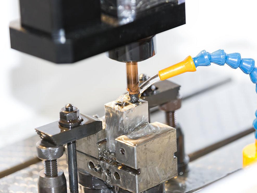
Wire EDM is suited to an internal slot, aperture, or contour when the wire can enter and exit through the part. The start hole must be located without weakening a critical wall, and the wire path must allow guides, flushing nozzles, workholding, and inspection clearance. A long narrow cut may experience changing debris conditions along its length. Wire tension, guide alignment, taper compensation, workpiece height, and support stiffness influence the finished geometry. After cutting, a thin wall may spring back, so measure the profile after unclamping.
The removal mechanism explains the access limit. A discharge melts a small volume at the tool-workpiece gap, and the dielectric must carry particles away before the next pulse. If the gap is blocked by debris or the electrode cannot approach the surface, the process may create arcing or an unverified pocket rather than a controlled internal feature. Inspect the route with a section view and define how the final condition will be cleaned and measured.
For a printed manifold component with an intersecting channel, choose EDM only when an electrode or wire can reach the intersection and the dielectric can be flushed through the route; verify the channel at the intersection, not only at the entrance. For a thin aerospace bracket component, choose wire EDM when the support and entry path preserve the wall; verify profile after unclamping. The correct route is determined by access, wall stiffness, debris evacuation, and final inspection rather than by the word “internal” alone.
An enclosed cavity needs a deliberate manufacturing opening or a different process before printing. A removable sacrificial feature may provide electrode entry and dielectric circulation, but it must be removed without changing the final datum or wall thickness. Document the opening, closure, cleaning, and inspection sequence in the drawing. If the design cannot support those actions, keep the feature as printed or redesign it instead of labeling it EDM-finished.
Sinker EDM Cavity Access
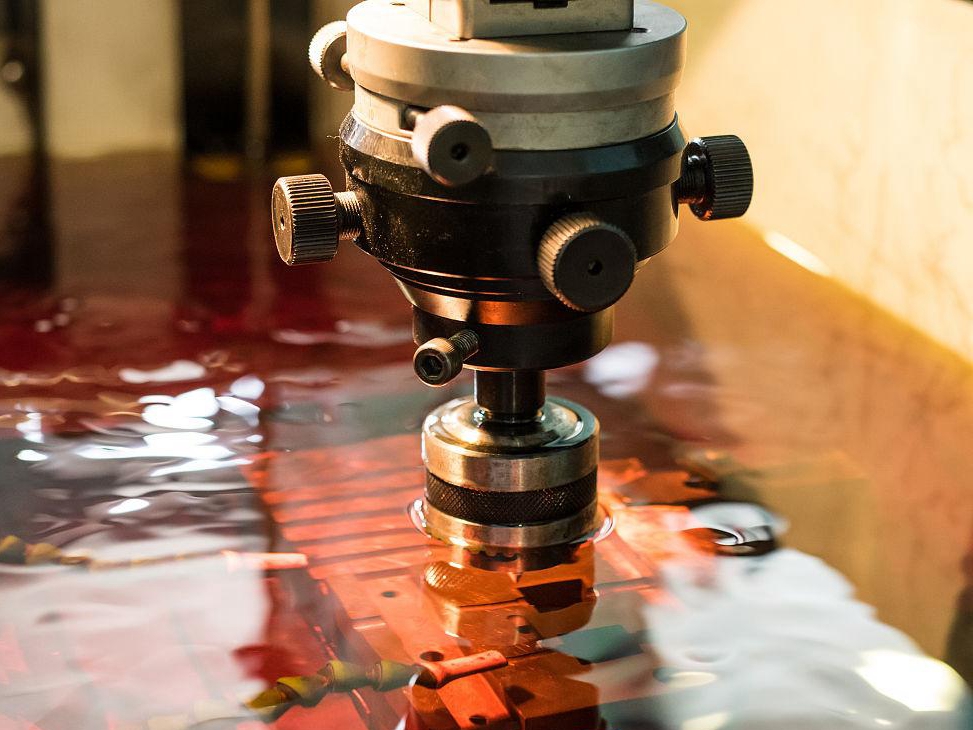
Sinker EDM can reach a blind cavity when a shaped electrode has a clear approach and the dielectric can circulate through the gap. Electrode form accuracy, wear, orbiting, flushing, and corner transfer affect the bottom and sidewalls. A deep pocket may show pitting or residue at its deepest point if debris cannot escape. Specify the electrode nose, approach direction, remaining allowance, pass sequence, cleaning method, and inspection depth. If the electrode cannot reach a surface or the instrument cannot measure it, state that limitation before quoting a final result.
Printed State, Support, and Cleaning
Internal geometry also depends on how the part was printed. Layer orientation, lack of fusion, gas porosity, residual stress, support-removal marks, and heat-treatment condition can change the response when material is removed. A flexible wall can be held in a false position by a fixture. A porous region can trap dielectric or particles. Define build orientation, material lot, heat-treatment state, support plan, electrical return, filtered flushing, drying, borescope access, and residue or flow verification before choosing the route.
Cleaning is a manufacturing requirement, not a final courtesy. A channel may need filtered flushing, compatible chemistry, drying, borescope inspection, flow testing, pressure testing, or residue analysis. If a later surface-treatment operation changes stock or closes a clearance, repeat the cleaning and inspection. Do not infer the internal condition from a bright opening or an open witness coupon.
Internal Feature Scenarios
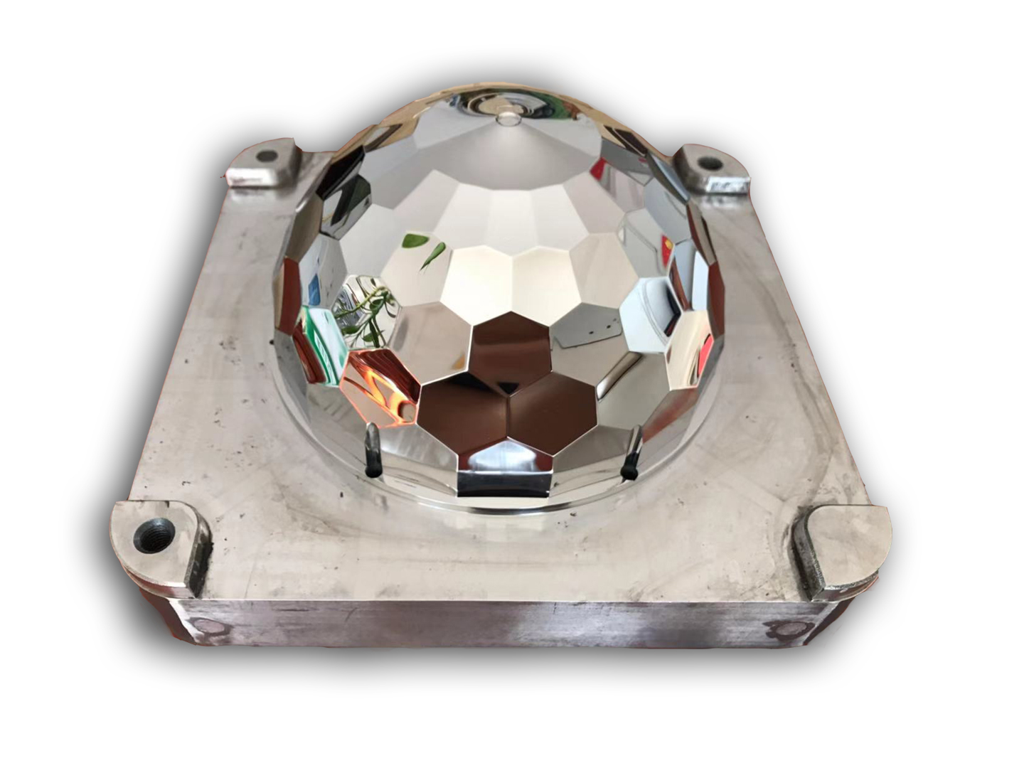
For an aerospace cooling insert, choose wire EDM when the passage profile has an entry route and low cutting force protects a thin wall; verify profile, recast, cleanliness, and flow or leak performance at the specified pressure and temperature. For a tooling cavity, choose sinker EDM when the shaped electrode reaches the floor and flushing is stable; verify floor depth, corner radius, roughness, and dimensional transfer. For a medical-development channel, choose EDM only after the contact, cleaning, sterilization, and approval boundaries are defined.
Provide CAD and drawing revision, section views, feature access, minimum wall thickness, material grade and lot, build orientation, heat-treatment state, allowance, quantity, electrode or wire plan, cleaning method, target roughness, dimensional tolerance, functional test, and acceptance authority. Request the parameter family, flushing record, unclamped dimensional report, residue evidence, and disposition of an inaccessible or contaminated feature. EDM can machine an internal geometry when access and evidence are designed together; it cannot validate a surface that no tool, fluid, or instrument can reach.
When comparing material capability, use the electrical discharge machining edm after the required property and section condition for this answer are fixed.
When planning the next process step, review the CNC machining service against the final geometry, inspection access, and release evidence described here.