What are the dimensional or geometric tolerances affected by heat treatment?
What are the dimensional or geometric tolerances affected by heat treatment?
Heat treatment can affect flatness, straightness, profile, hole position, wall thickness, angularity, concentricity, and datum relationships when residual stress, thermal strain, phase change, or fixture release moves the printed part. The amount is geometry- and material-specific. Choose a thermal route only after identifying the dimensions that control assembly or function, then measure the free state after treatment and after final machining. Coordinate the decision with the heat-treatment route and the final machining state.
Why Dimensions Move
Residual stress from rapid melt-pool cooling is restrained by supports, the build plate, and adjacent material. When a support is removed, elastic strain can release and bend a wall. During heating, different section thicknesses create gradients; during cooling, contraction and phase transformation can add strain. A fixture can reduce movement in one direction while introducing another constraint. Heat treatment changes this balance because time at temperature allows stress redistribution and, in some alloys, phase evolution.
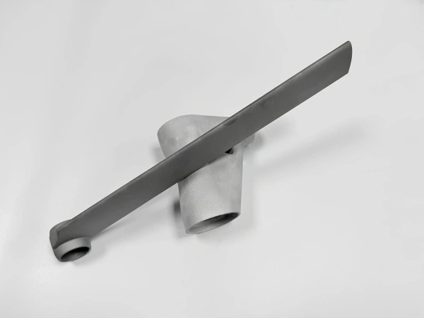
For a long thin bracket, select heat treatment when dimensional release is the controlling risk and verify the unclamped profile before machining. For an H13 insert, choose hardening and tempering from the cavity tolerance, corner radius, polish allowance, and crack risk, then map cavity datums after the cycle. A solid witness coupon cannot prove either geometry unless its restraint and section represent the component.
Tolerance Planning
State the measurement condition: attached or free, clamped or unclamped, before or after cleaning, rough-machined or finished, and at what temperature. Define datum sequence, instrument, uncertainty, sampling points, and acceptance limit. A CMM or scan report taken on a fixture should identify the fixture and verify the released state. Internal channels may need CT or a replica because a stylus cannot reach every surface.
Coordinate rough machining and final machining with the CNC route. Leave measured stock only where the drawing permits it; excessive stock removal can change wall thickness and balance. If HIP is included, treat it as a separate dimension-changing operation and inspect again. HIP may reduce suitable closed porosity, but it does not remove a dimensional error or an open surface defect.
Failure Controls
For a ring with a precision bore, select heat treatment before fixing the machining datums because bore position, roundness, and concentricity may change as stress is released. Verify the bore with a calibrated CMM or gauge after the final cut. For a thin lattice or channel plate, choose the route from minimum wall, support access, and cleaning method, then verify open area, wall thickness, and profile in the final state.
For a thin mounting flange, select the treatment and fixture together when parallelism or bolt-hole position controls assembly. Measure the flange free on a stable datum before treatment, map the same points after cooling, and reserve machining stock only where the drawing allows correction. For an internal channel plate, select CT or a validated replica when the functional opening cannot be reached by a probe. Report the measurement state, because a clamped scan can show a passing shape while the released part is out of tolerance.
Build a tolerance budget before selecting the cycle. Separate machine accuracy, support-removal movement, thermal movement, machining variation, surface finishing, and measurement uncertainty. A 0.10 mm profile requirement cannot be assigned entirely to heat treatment if the scan uncertainty is 0.05 mm or if final polishing removes an unrecorded amount of stock. Establish repeatable inspection points, use the same coordinate system before and after treatment, and identify which variation is correctable by machining. When no correction remains, the measured free-state result governs the disposition.
Internal geometry needs a planned inspection route. Use CT when density, voxel size, and feature size can resolve the channel, or use a validated gauge, fluid-flow test, or replica when that method is more appropriate. A surface scan cannot prove a hidden bore, and a single end-to-end flow value cannot prove local wall thickness. Tie each acceptance claim to the method that can actually observe the feature, then retain the raw report with the final dimensional record.
Control bowing with orientation, support design, thermal loading, fixture review, and before-and-after dimensional maps. Control hole drift with machining allowance, a protected datum strategy, and inspection after release. Control corner cracking with alloy-specific hardening or cooling, radius review, and crack screening. Control oxidation-related measurement error with atmosphere, cleaning, and consistent surface preparation. If a tolerance fails, identify the mechanism before authorizing another cycle.
RFQ Information
Provide CAD and drawing revision, alloy and lot, additive route, orientation, support state, section thickness, critical datums, geometric tolerances, temperature, fixture, thermal cycle, cooling, HIP status, machining allowance, surface, quantity, inspection method, and acceptance authority. Request furnace records, calibration, witness coupons, free-state CMM or scan data, final dimensions, hardness or tensile evidence, NDT where required, and deviation disposition.
Use a project-specified measurement method and confirm whether ASTM E8/E8M, ASTM E18 or E384, ASTM E466, or AMS 2750 applies to the evidence. State the measurement temperature, datum sequence, instrument uncertainty, and final acceptance limit. Release the part in the final state. A dimension that passes before heat treatment but fails after polishing, coating, or machining still requires final-state disposition.
If this question concerns a failure mechanism, compare the heat-treatment service after the suspected cause and test condition are identified.
For a controlled production decision, request the CNC machining service when the final state and deviation path need traceable evidence.