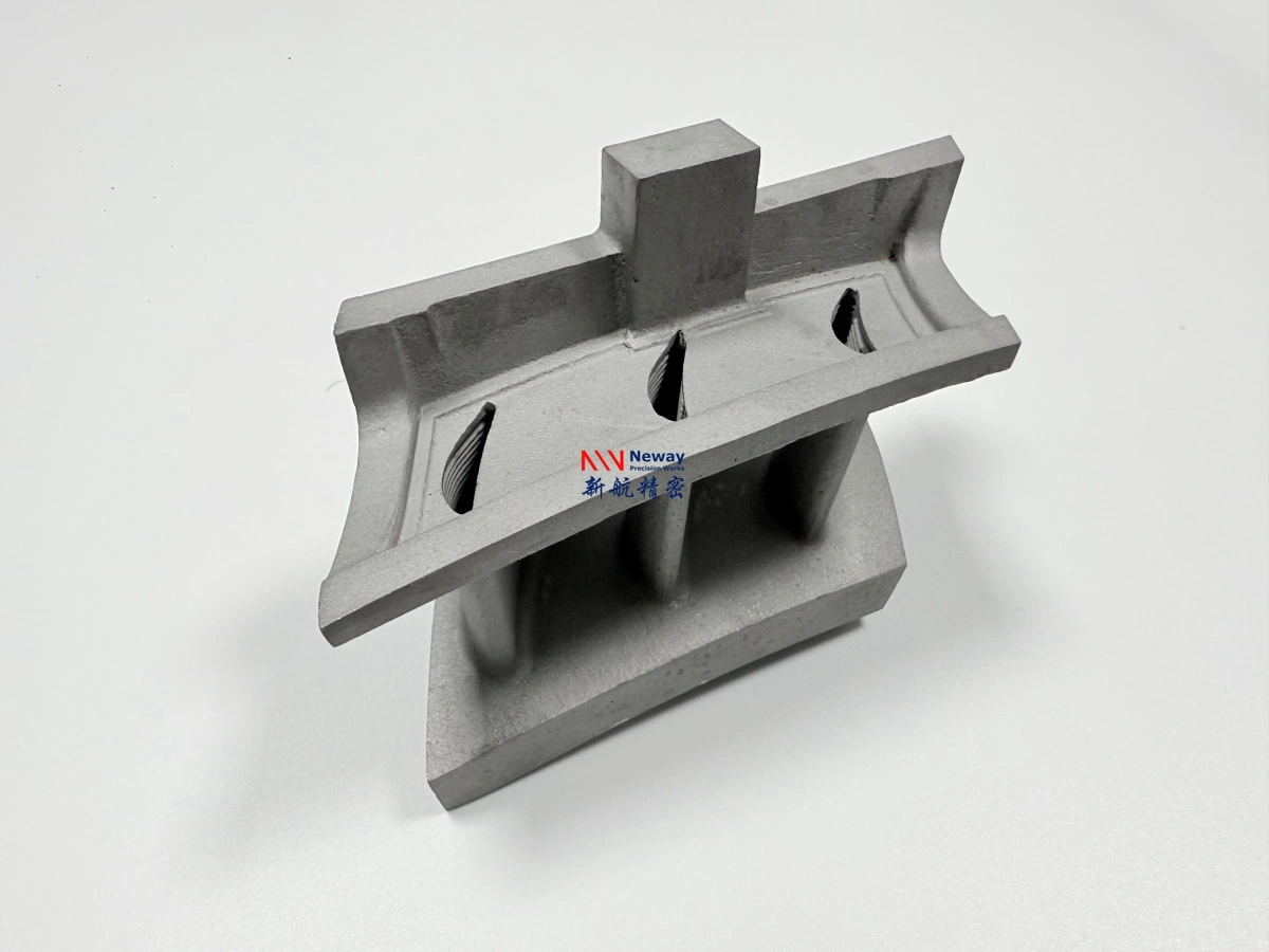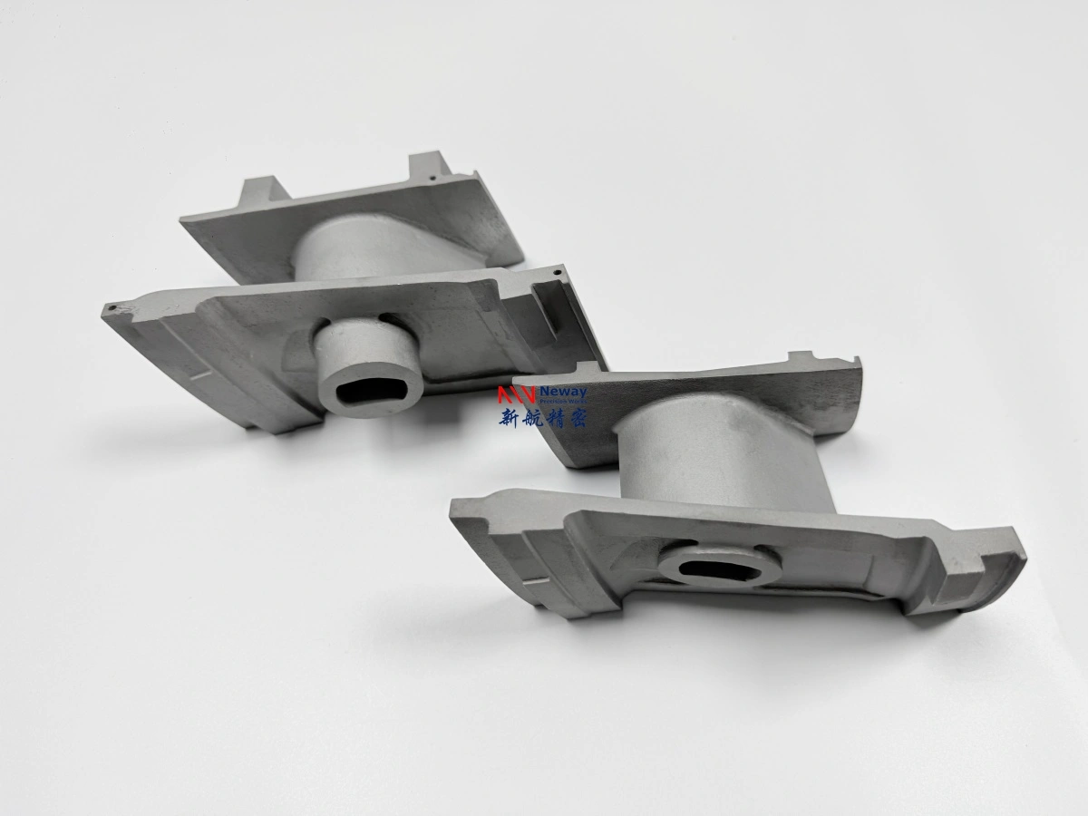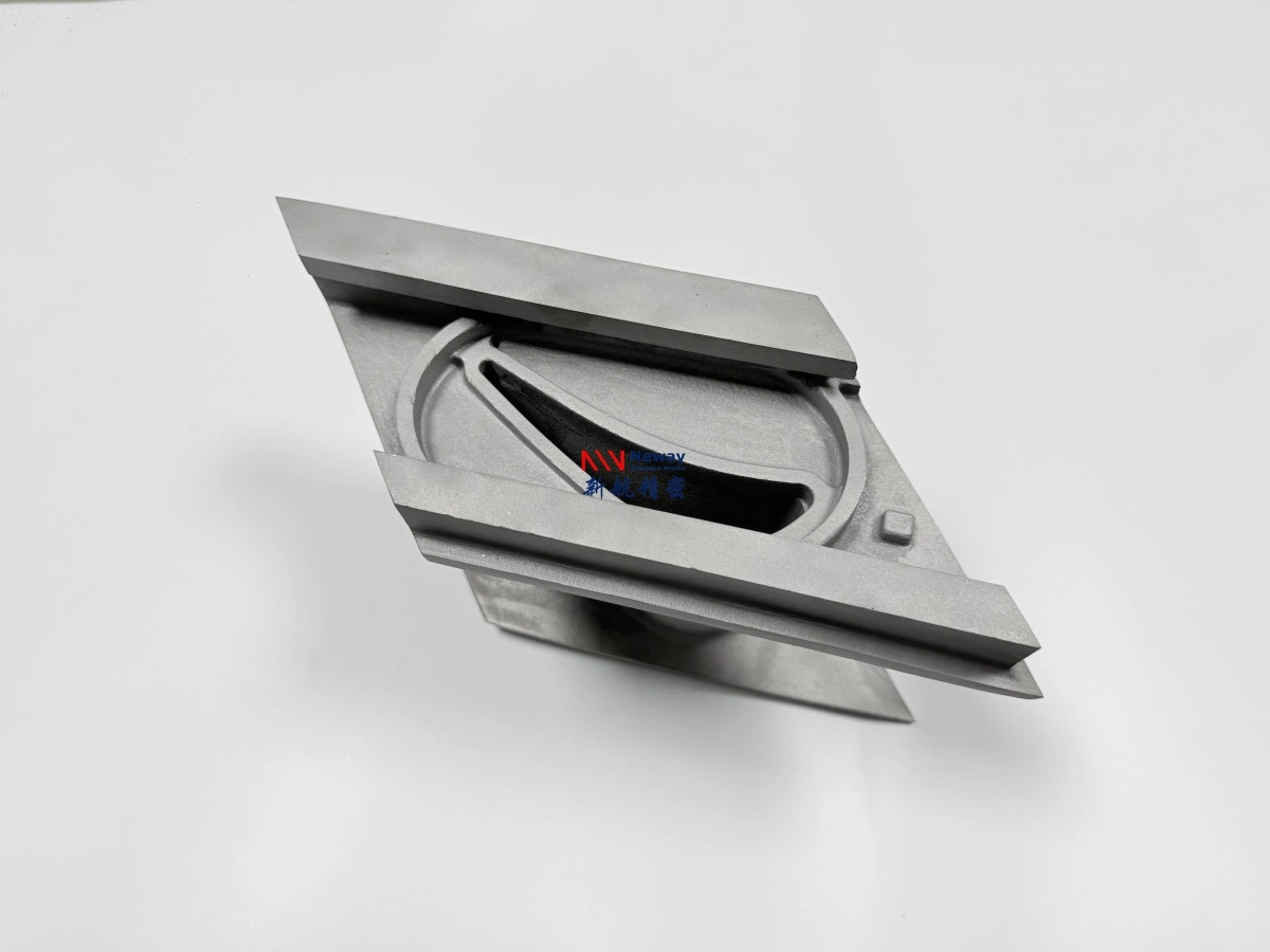
GH3536 3D Printing: Behavior and Limits
GH3536 3d printing suits a burner liner to about 900 °C in structure and 1,100 °C in clean oxidation, at the cost of machinability. It is a nickel–chromium–iron superalloy; density is 8.22 g/cm³ and expansion 13.9 µm/m·K. It is not a pressure-vessel material and not a direct substitute for Inconel 718 where strength per section matters. The sections treat it as behavior at temperature, not a grade recommendation.
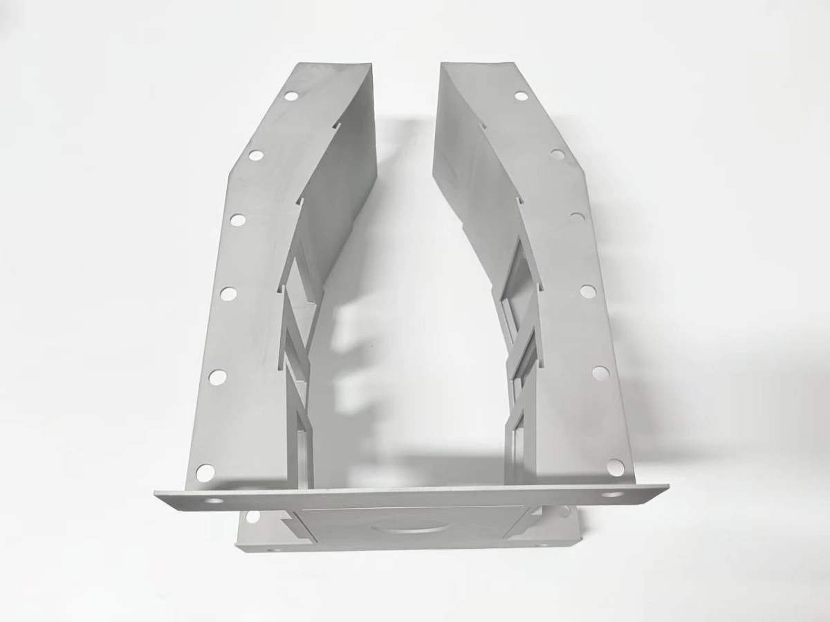
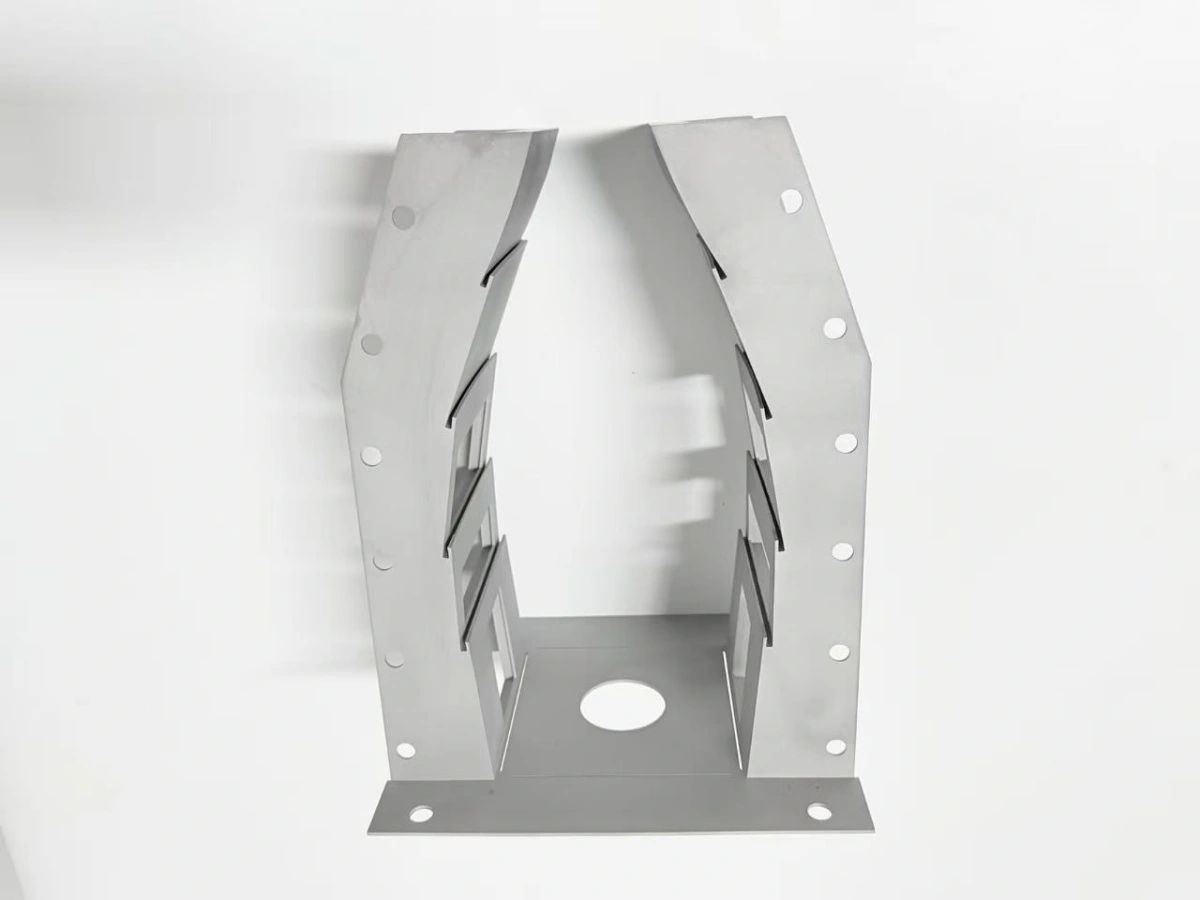
Why choose GH3536 for a burner liner?
GH3536 is chosen when a part needs moderate high-temperature strength plus oxidation resistance, and the alternative grades either cost more or machine worse. The alloy keeps usable strength to about 900 °C in structural service, and its oxide scale stays protective to roughly 1,100 °C in clean combustion gas.
Against 316L the trade is temperature. A 316L liner is cheaper and easier to weld, but it loses useful strength above about 600 °C and scales faster in cycling service. Against Inconel 718 the trade is strength per section and machining cost: 718 holds more load at 700 °C but is harder to cut and needs tighter process control.
The alloy also carries a density penalty. At 8.22 g/cm³ a printed liner is heavier than a fabricated 316L part of the same envelope, which matters on a moving assembly and not on a static test combustor.
The gh3536 properties that matter on a drawing are the creep strength at 900 °C, the oxidation scale stability to about 1,100 °C and the thermal expansion of 13.9 µm/m·K. A grade with a lower expansion would move less per cycle but usually trades away strength at temperature.
For a burner liner the deciding condition is usually the wall. A 1.8 mm wall in GH3536 carries the thermal gradient without local hot spots. The expansion of 13.9 µm/m·K keeps the flange and window frames in a predictable range across a cycle.
How does GH3536 behave in laser powder bed fusion?
GH3536 3d printing in laser powder bed fusion (PBF) prints with good crack tolerance and a narrow parameter window, which is why it is often used for thin walls and fine features. The alloy is not as forgiving as 316L on residual stress, and sections above about 20 mm need a stress plan before the build is released.
The build runs at 40 µm layers with oxygen kept at or below 100 ppm in the chamber. Above that level the oxide films on the powder raise porosity and can seed lack-of-fusion defects in the wall.
As-built density typically reaches 99.0–99.5 % with a qualified parameter set, and HIP closes the remaining porosity to 99.5 % or better. The number matters for a liner because a 1.8 mm wall has little section to absorb a pore.
Nickel superalloy 3d printing also changes the inspection plan. A GH3536 wall is checked for lack-of-fusion at the window edges, where the laser track turns and the local cooling rate drops, rather than by a density coupon alone. A used powder lot also changes the print window, so the lot number travels with the build record, and the window edge movement follows the thin wall distortion note.
The powder itself is the second variable. Reused powder raises the oxygen and nitrogen content, and the alloy responds with slightly higher strength and lower ductility; the powder lot is therefore part of the material record, not a purchasing detail.
What do solution treatment and HIP change?
Solution treatment and hot isostatic pressing (HIP) change the alloy from an as-built state with residual stress and aligned porosity into a stable, near-fully dense condition. The solution treatment runs at 1 180 °C for 1 h, and the HIP cycle at 100 MPa and 1 180 °C for 3 h. The sequence matters more than either step alone, because HIP cannot close porosity that the surface has already sealed and cannot remove stress that the fixture has locked in.
- Solution treat for 1 h at 1 180 °C to dissolve the build structure and release stress.
- HIP at 100 MPa and 1 180 °C for 3 h to close internal porosity.
- Furnace cool below 300 °C before the door opens, to avoid a new gradient.
- Re-measure the datum faces before machining, because the cycle moves the part.
The furnace record matters as much as the cycle. A chart that shows the 1 180 °C hold, the 100 MPa pressure trace and the cool below 300 °C is the evidence that the material behavior happened. A certificate without the chart is only a claim. The cycle also leaves the alloy softer and more uniform than as-built, and the heat treatment route also sets the condition for the HIP record that the operator keeps.
How does the alloy machine after printing?
GH3536 machines worse than 316L and better than Inconel 718, with a strong tendency to work-harden under a light pass. The practical rule is to keep the cut below the hardened layer and to take the allowance in one or two passes rather than many spring passes. The table lists the machining window for a printed liner; the target and the acceptance band are separate.
| Parameter | Condition | Target | Band (unit) |
|---|---|---|---|
| Face allowance | As-built flange | 1.5 mm | 1.0–2.0 mm |
| Hole allowance | Drilled after HIP | 1.0 mm | 0.8–1.2 mm |
| Surface finish | Finish pass | Ra 1.6 µm | Ra 1.6–3.2 µm |
| Flatness | Flange face | 0.05 mm | 0.05–0.10 mm |
| Thread | M4 in GH3536 | 1.5×D | 1.5–2.0×D |
The machining allowance is also a schedule item. GH3536 removes about half the volume per hour that 316L does on the same five-axis cell, and the flange and window faces are the slowest features because they need a single setup.
Tool wear is the other cost. The alloy work-hardens and abrades carbide edges, so a finishing insert that lasts a full 316L batch may need changing mid-batch on GH3536. The thin wall design rules already assume that the machined face, not the printed face, is the datum.
Where does GH3536 stop being the right choice?
GH3536 stops being the right choice above about 1,100 °C in oxidising gas, in sulphur- or chloride-bearing atmospheres, and where the section needs more strength than the alloy can carry at temperature. Those conditions move the decision to a higher-strength nickel grade or to a coating, not to a thicker GH3536 wall.
The comparison that decides most projects is against Inconel 718. At 700 °C, 718 carries roughly twice the yield strength of GH3536, so a load-bearing bracket that passes in 718 will not pass in GH3536 at the same section. The reverse trade appears in cost and machinability, where GH3536 wins.
The Hastelloy X alternative is the same family under another trade name, so the comparison is commercial rather than metallurgical. A buyer who specifies Hastelloy X and receives GH3536 should expect the same behavior within the standard chemistry range, and the mill certificate, not the name, decides the acceptance. Against 316L the limit is simpler: 316L is adequate to about 600 °C and cheaper, so a low-temperature liner that never sees 700 °C does not need GH3536 at all.
Against a cast route, printing wins on two conditions. It wins when the wall is below 2.0 mm and a casting would not fill it cleanly, and when the first article is needed in weeks rather than months. Casting wins when the batch runs above a few hundred parts, and when the section is thick enough that a near-net casting needs less machining than a printed blank.
There is also a geometry condition. A very thick section, above about 40 mm, gains less from the alloy because the thermal gradient and the HIP cycle dominate the result, and a cast or wrought route may be the better comparison.
When does this material judgment not hold?
This judgment does not hold when the duty includes thermal shock from a cold start, when the powder lot is unknown, or when the part is a pressure boundary. Each of those removes the assumption that the alloy behavior, not the process record, decides the outcome.
It also does not hold for a repair route. A welded repair on GH3536 needs its own heat treatment and its own inspection, and the material behavior described here applies to the original build, not to the repaired zone.
The oxidation limit is a service estimate, not a commitment. The 1,100 °C figure is scale stability in clean gas, and a real combustor with sulphur or particulates can degrade the scale well below that number.
GH3536 3d printing also depends on the machine. A parameter set qualified on one laser system does not transfer unchanged to a second system, so the material judgment is tied to the build record.
Finally, the numbers here come from ASTM B435 and ASM Handbook Vol. 4, plus the qualified parameter set; a different powder supplier or a different machine changes the print window, and the material judgment has to be re-run on the new build rather than copied.
Send the duty conditions, the section and the joining route. Neway compares them against this material behavior, marks where GH3536 holds and where a higher grade is needed, and returns a route with the heat treatment and machining window for that section.
FAQs