How Do You Control Burner Liner Distortion?
Burner liner distortion control uses three Ø3 mm tie bars, solution treatment before release, and 2.0 mm of face stock. Together they hold the window openings within 0.3 mm for this geometry.
Where Does Burner Liner Distortion Control Start?
The first source is the powder bed, not the machine. A 1.8 mm wall cools faster than the 3 mm window frames beside it, and that mismatch sets up a bending moment which grows as the part is cut from the plate. The build stresses are real before anyone touches the liner.
The second source is the solution treatment. Heating to 1,180 °C relaxes those build stresses, but the part also creeps under its own weight while it is soft. A liner supported only at its base will sag between the window frames, and the sag does not reverse on cooling.
Machining adds the third source. Clamping at the flange distorts the openings if the jaws are too strong, and releasing the clamps after the cut lets the wall spring back. The spring-back is why a liner can measure true in the fixture and out of tolerance on the bench.
The alloy sets the scale of all three. GH3536 is the nickel-chromium-iron-molybdenum grade listed in ASTM B435, and its thermal expansion is close to 13.9 µm/m·K over the range the treatment covers. ASM Handbook Vol. 4 covers the same stress relief for thin walls in this family of alloys.
Which steps hold the window openings?
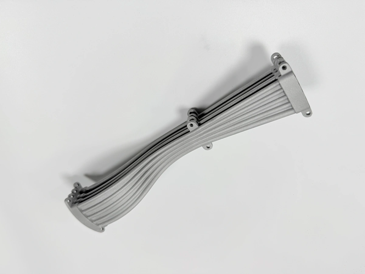
Burner liner distortion control starts with the tie bars. Three Ø3 mm bars bridge the window openings while the part is printed, and they stay in place through solution treatment. They are cut only after the part has cooled and been measured, so the openings are held while the stresses relax.
Solution treatment comes before release. The liner is treated at 1,180 °C for 1 h, then cooled in the furnace to below 300 °C. Cutting the tie bars before this cycle would let the openings move with nothing to resist them, and no later step could pull them back.
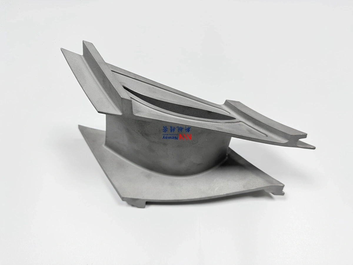
Stock on the assembly faces is the third step. We leave 2.0 mm on the flange faces and 1.0 mm in the holes, so the final cut removes the deformed skin rather than trying to hold a finished surface true. The stock is not waste; it is the allowance that absorbs what the thermal cycle moves.
Measurement closes the loop. A blue-light scan before machining records the as-treated shape, and a second scan after machining shows what the cutter removed. The coordinate measuring machine (CMM) check on the finished part then confirms the 0.3 mm limit on the burner liner opening distortion, and the same setup checks the flange flatness.
The order matters more than any single step. Tie bars cut before treatment, or stock removed before the stress relief, and the openings move with no control left. The sequence is the method, not a set of independent tricks.
When does tie-bar control not hold?
Burner liner distortion control is sized for this geometry. A liner with more than three windows, or with windows on two axes, needs a different bar layout and a new distortion check. The three-bar pattern is a working answer here, not a universal rule.
The control also stops working when the wall is thinner than 1.5 mm. A thinner wall bends more under the same treatment, and the bars cannot carry the load without adding distortion of their own. The design rules for thin-wall superalloy parts cover the section that is needed below that thickness.
A different alloy changes the answer. A crack-sensitive grade may need a slower cooling cycle, and the alloy's expansion sets how much the openings move during treatment. The bars hold the geometry; they do not change the metallurgy.
Tie bars also do not fix a bad build. If the powder-bed stresses are already high, cutting the bars releases stored energy and the openings move anyway. The distortion in superalloy printing note covers how the build parameters drive that, which is why the distortion check starts with the print recipe.
Send the window layout, the gas temperature and the alloy. This note covers distortion control only; wall thickness and alloy selection are separate questions. We will confirm the tie-bar pattern and the stock allowance for the geometry, and quote the printed liner through our superalloy 3D printing route.
.webp)