
How Is Burner Liner Window Machining Done After Printing?
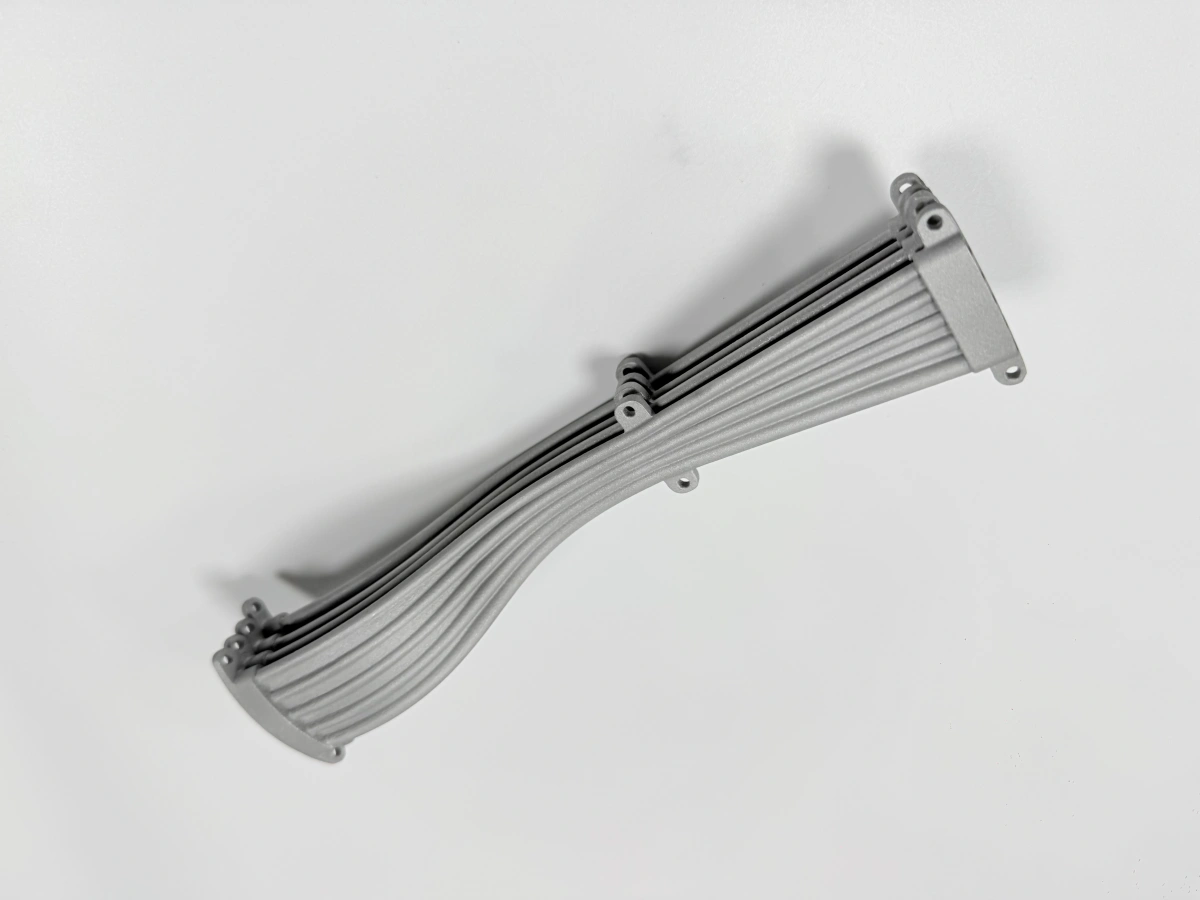
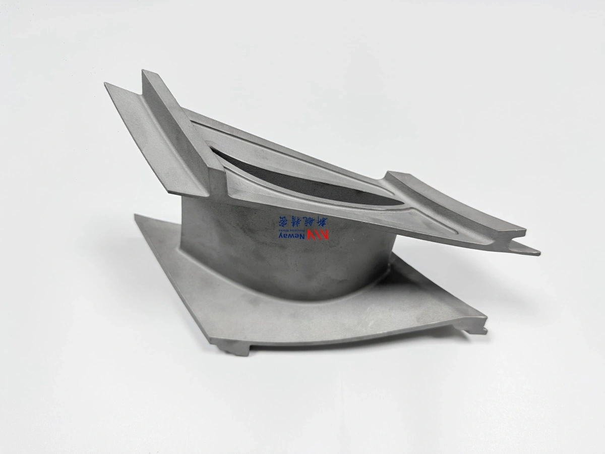
Burner liner window machining cuts the window and flange faces in one setup from the assembly interface. That leaves 1.0 mm on the faces and 0.4 mm in the holes before the final pass. Cutting both faces from the same datum keeps the openings and the flange in one tolerance frame.
Which Datum Controls Burner Liner Window Machining?
The assembly interface is the datum. It is the face that sits on the test rig, so every other surface is machined from it rather than from the print plate. A liner that is cut from the build plate instead can be flat on the bench and still sit crooked on the rig.
The datum is established before any cut. The flange face is probed at six points, a best-fit plane is set, and the window openings are measured relative to it. If the as-printed flange is outside the stock allowance, the part is scrapped before machining rather than after.
One setup carries both faces. The window frames and the flange face are cut in the same clamping, so the 0.05 mm flatness and the ±0.05 mm hole position come from one frame. Reclamping between faces would add a second setup error to the stack.
The general tolerances are ISO 2768-1, and the surface texture is called out to ISO 4287. The drawing may tighten the flange and the window seat; everything else stays on the general tolerance.
How much stock is left after printing?
Stock is set per surface. The flange faces keep 1.0 mm, the window seats keep 0.8 mm, and the holes keep 0.4 mm. The stock is measured on the blue-light scan before the part reaches the machine.
The 1.0 mm on the faces is not arbitrary. A 1.8 mm wall moves during solution treatment and hot isostatic pressing, and the flange face picks up a waviness of a few tenths. One millimetre removes that layer in one pass without cutting into the finished section.
The 0.4 mm in the holes is the minimum for a clean bore. Less stock risks a cut that only skims the surface, and a skimming cut leaves a tapered hole. The 0.4 mm allows a full-diameter pass with a rigid tool.
The window seats keep 0.8 mm, enough to clean the seat and leave a flat land for the quartz window. Cutting the seat in the same setup as the flange face keeps the seat parallel to the assembly interface.
Clamping stays at or below 0.5 MPa. A 1.8 mm wall springs under a heavier clamp, and the cut then measures true only while the part is held. Soft jaws and a plaster fill spread the load over the wall.
When is printed geometry not worth machining?
Burner liner window machining is not always the right step. If the drawing only needs the openings to clear a quartz window and the flange flatness is not called out, the as-printed part may be acceptable with a light fettling pass.
The comparison is straightforward. A printed liner needs about 3 hours of five-axis thin-wall machining, while a fettled liner needs 30 minutes of hand work but keeps the print tolerance. The choice depends on whether the interface is structural or just a cover.
Thin walls set the limit. Below 1.5 mm, the clamping force that the wall can take falls faster than the stock that has to be removed, and the part moves under the cutter. The design rules for thin-wall superalloy parts explain why those liners are better redesigned with local thickening than machined thinner.
A different alloy can also change the answer. A crack-sensitive grade may need a stress relief before machining, and the extra cycle adds a day to the route without changing the cut itself. The distortion in superalloy printing note covers when that relief is needed.
Inspection follows the cut. A blue-light scan after machining confirms the printed flange flatness, and a coordinate measuring machine (CMM) check confirms the window position. The M4 threads are checked with a go/no-go gauge, and the thread depth is set to 1.5×D so the bolt does not bottom out.
This note covers machining after printing; wall thickness and distortion control are separate questions. Send the drawing with the datum, the tolerance callouts and the window layout. We will confirm the stock allowance and the setup, and quote the machined liner through our superalloy 3D printing route.
.webp)