
Thin Wall 3D Printing Distortion: Where It Starts
Thin wall 3d printing distortion depends on where a thermal gradient meets a free edge: a 1.8 mm liner moves up to 0.3 mm. In an open liner the wall has nothing on one side to hold it, so each thermal cycle leaves a little more movement behind, and the movement concentrates at window corners and flange rims. The error grows with each thermal cycle and concentrates where the wall is free.
A 1.8 mm GH3536 liner is a useful example: the wall is thick enough to print, thin enough to move, and open enough that the free edge is always the weakest point.
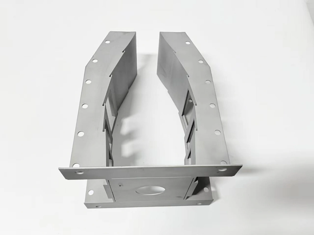
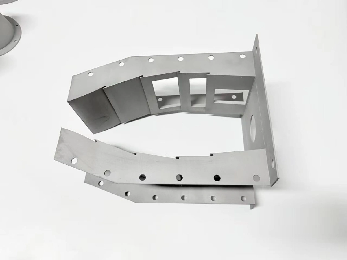
What does thin wall distortion look like on a liner?
On a liner the distortion shows up as three measurable symptoms. The flange loses flatness, the window frames lean, and the wall bows between the frames. None of the three is visible as a crack; they are shape errors that appear only when the part is measured against a datum.
The first symptom is the cheapest to see. A flange that reads 0.1 mm out of flat on a surface plate has already moved at the rim, because the rim cools faster than the wall. The second is a window frame that is no longer square to the flange; the frame follows the wall as it curls, and the error grows with each thermal cycle.
The third symptom is the wall bow. Between two frames, a 1.8 mm wall can bow 0.2–0.3 mm without any visible mark, and the same thin wall 3d printing distortion reappears at every window corner.
The thin-wall design rules show which frame and rib sizes keep that bow inside the criterion. A liner that passes a visual check can still fail the opening criterion of 0.3 mm, which is why the number is measured, not judged.
Where does the residual stress come from?
Residual stress comes from three sources that arrive in sequence: the melt, the fixture, and the furnace. The melt creates the first gradient, the build plate holds the part while it cools, and the furnace adds a second gradient when it heats and cools the section again.
The thin wall distortion mechanism is a gradient meeting a constraint, and powder bed fusion (PBF) makes both terms visible. In PBF the laser melts a track and the track contracts as it solidifies. The layer below is already cold, so the contraction is constrained and becomes stress. On a 1.8 mm wall the constraint is weak in the thickness direction and strong along the length, which is why the wall bows rather than shrinking evenly.
The build plate adds a second constraint. The part is anchored at the base, so the first layers cannot move; by the time the plate is cut, the stress is locked into the wall. A stress relief before cutting would release it, but the relief itself runs at 1,180 °C for 1 h, and that cycle is the next source of movement.
The material sets the scale. The LPBF thermal stress term is set by the melt pool, not by the furnace, so it is fixed before the part ever sees a heat treatment. GH3536 expands about 13.9 µm/m·K between 20 °C and 100 °C, and the expansion is not the problem by itself; the problem is that the free edge and the restrained base expand by different amounts at the same temperature.
Why do solution treatment and HIP add to the movement?
Solution treatment and HIP add movement because each one runs the part through a full thermal cycle while it is still open. The distortion after HIP is the part of the movement that the hot isostatic pressing cycle adds on top of the solution treatment. The solution treatment releases the build stress at 1,180 °C for 1 h, and the release is not uniform: the free edge moves first and the restrained base moves last.
The HIP cycle adds a second, slower movement. At 100 MPa and 1,180 °C for 3 h the wall creeps under the pressure, and a wall that was straight after solution treatment can bow during the hold. The effect is small per cycle but cumulative, which is why the pre-HIP scan matters as much as the final one.
The furnace schedule controls how much movement happens. A ramp held at 5 °C/min and a cool that opens the door below 300 °C keep the gradient across the wall small; the stress relief note covers the same schedule for other superalloys. A faster ramp does not save time overall, because the straightening that follows costs more than the hours saved.
There is a second-order effect at the window frames. The frame is thicker than the wall, so it heats and cools more slowly, and the mismatch between frame and wall is where the corner distortion concentrates.
How do two scans separate thin wall 3d printing distortion?
Two scans separate the causes because each one is taken at a different point in the thermal chain, an approach also used on distortion and thin walls in other grades. The pre-HIP scan is taken after solution treatment, and the final scan is taken after machining; aligning both on the machined flange leaves two difference maps instead of one number.
The first map shows what moved during HIP. If the window frame leans between the pre-HIP scan and the final scan, the cause is the HIP cycle and its fixture, not the machining. The second map shows what moved during machining, which is usually a clamping effect rather than a thermal one.
The alignment datum is the machined flange, not the raw print. Using the raw flange would mix the machining allowance into the map, and the map would then show a movement that is really stock removal.
The release decision follows the maps. The target is 0.2 mm at the opening and the acceptance limit is 0.3 mm, so a movement between the two numbers goes to a second measure before rework, and a movement outside 0.3 mm goes to rework or scrap. The record shows which cycle produced it.
| Control lever | Cast route | Additive route | Effect on movement |
|---|---|---|---|
| Thermal gradient | Mold preheat | 5 °C/min ramp | Lower gradient, less bow |
| Constraint | Gating and chill | Build plate and supports | Controls where stress locks |
| Stress relief | After shake-out | 1,180 °C/1 h before HIP | Releases build stress |
| Densification | Riser feed | 100 MPa HIP, 3 h | Closes porosity, adds creep |
| Verification | Sectioning | Two scans on the flange datum | Separates causes |
The table is the short version of the article: the cast route controls the same four variables through different levers, and the verification step is what makes either route auditable.
When does the mechanism stop explaining the error?
The mechanism stops explaining the error when the section is no longer thin, when the alloy is no longer a nickel superalloy, or when the movement comes from the fixture rather than the metal. Each of those cases needs a different explanation and a different control.
A thick section does not bow the same way, because the thermal gradient across the wall is smaller and the restraint is distributed. A closed section behaves differently again: the powder cannot escape, and the internal pressure during HIP becomes the dominant term.
The alloy matters as well. A cobalt-based grade with a different expansion coefficient will move by a different amount at the same gradient, and the 13.9 µm/m·K figure is a GH3536 number, not a universal one. The same caution applies to a part that was stress-relieved in a fixture that was not flat: the map will show movement that the metal did not cause.
Outside those limits the mechanism is still a useful starting point, but it is not a prediction. The honest answer is to measure the part at each stage and let the two maps decide, rather than to promise a number from a material data sheet.
Inside the limits, thin wall 3d printing distortion is controlled by a small set of numbers: a 1.8 mm wall, 40 µm layers, a 1,180 °C/1 h solution treatment, a 100 MPa HIP, and an opening criterion of 0.3 mm checked on the scans. The HIP heat treatment note gives the cycle in more detail. Those five numbers are the practical summary of the mechanism.
Send the drawing with the wall thickness, the window layout and the alloy, for example GH3536. Neway reviews the section against the mechanism, proposes the scan stages and the datum, and returns a route that states where the movement will be measured. The review starts with the Inconel printing buyer guide and continues through the superalloy 3D printing service once the section is fixed.
FAQs