3D Printed Burner Liner: From Powder to Inspected Part
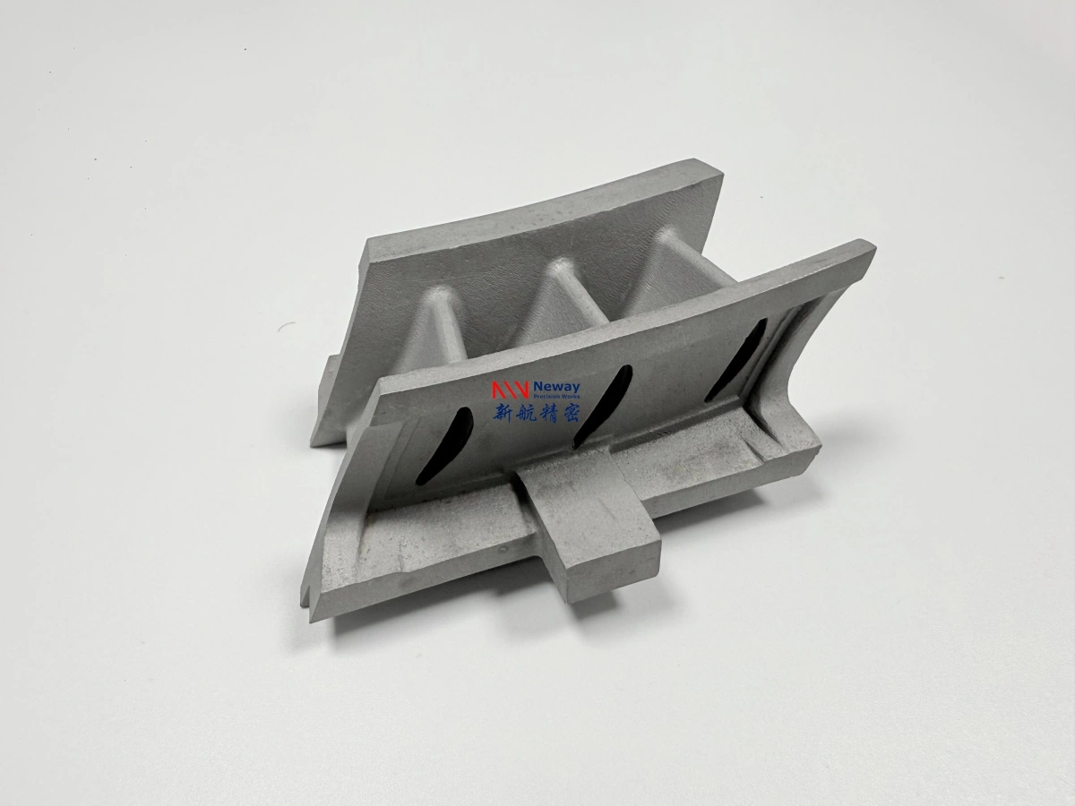
A 3d printed burner liner moves through 5 stages before release: print, solution treat, hot isostatic press, machine the interfaces and scan twice. For the GH3536 liner in this case the wall is 1.8 mm, the layers are 40 µm, and release asks for a 0.05 mm flange flatness against a 0.10 mm acceptance band. The order is fixed: skip a stage and the risk lands on the next one, where it costs more to remove.
- Print the liner in GH3536 with 40 µm layers.
- Relieve build stress at 1,180 °C for 1 h.
- Hot isostatic press at 100 MPa for 3 h.
- Machine the assembly interface in one setup.
- Scan, measure and release against the drawing.
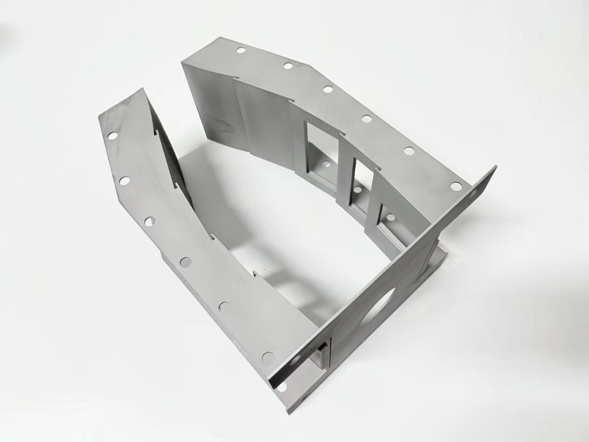
Why print a burner liner instead of welding sheet metal?
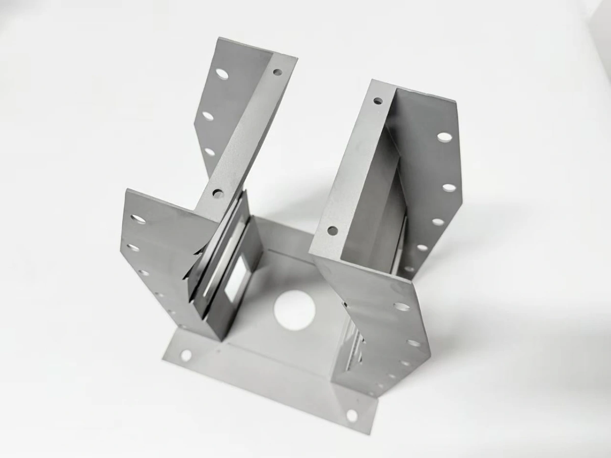
Printing removes the welds that a fabricated liner puts across its hottest wall. A welded liner needs formed panels, a fixture, a weld sequence, a stress relief and a straightening pass, and every seam leaves a heat-affected zone where oxidation starts. Hot-section superalloy parts printed in one piece carry no seam on the gas side.
The trade is thermal, not mechanical. A printed liner comes off the machine with integral flanges and window frames, so it skips weld prep and panel forming, but it then needs two furnace cycles and two scans. Those steps replace the weld and straighten sequence, and they are the reason the route is scheduled as a chain rather than a queue of jobs.
That is why a metal 3d printing burner liner project starts with a build review rather than a purchase order: the thermal chain decides the cost and the risk, not the machine hours.
Volume decides the argument. One liner or a five-piece prototype is cheaper printed because there is no tooling, while a cast liner needs a pattern and a pour and opens at 4–6 weeks. Above a few hundred pieces a year the tooling amortizes and casting or fabrication can win again.
What must be checked before the build starts?
The drawing is checked against four build limits before any powder is loaded. A liner that misses one of them is redesigned or split before a machine slot is booked.
- Wall thickness: 1.8 mm on this liner, 1.5 mm floor.
- Overhang: 45° from vertical.
- Powder escape: 3 mm minimum opening.
- Envelope: inside the 400 × 250 mm plate.
Wall thickness is the first limit. This liner runs 1.8 mm, and 1.5 mm is the practical floor for an open section that must hold flatness after hot isostatic pressing (HIP), measured on the coupon as well as on the part; below that the frames need local thickening. The thin-wall design rules give the frame and rib sizes that support the floor.
The powder is the second input. The GH3536 laser powder bed fusion (LPBF) lot is checked against ASTM B435 chemistry before the build, and the machine runs one parameter set for the whole job: 40 µm layers, a 285 W laser and 960 mm/s scan speed. One set keeps the thermal history uniform from the first layer to the last. The GH3536 LPBF powder certificates travel with the build record.
| Build check | Limit for this liner | Consequence if missed |
|---|---|---|
| Wall thickness | 1.8 mm (floor 1.5 mm) | Section moves after HIP |
| Overhang angle | ≤45° from vertical | Dross on the window frame |
| Powder escape opening | ≥3 mm at every corner | Residual powder, heavy part |
| Build envelope | Inside the 400 × 250 mm plate | Split build, extra seam |
| Powder chemistry | ASTM B435 for GH3536 | Off-chemistry melt |
The table is an inspection gate, not a wish list: a build slot is booked only after all five rows pass.
The check is repeated when the drawing revision changes. A new window layout moves the support plan, a new alloy moves the HIP cycle, and a new wall thickness moves the machining stock, so the build review is reissued against the new revision before a second build is booked.
How is the liner oriented, supported and treated?
The liner stands on its base flange so the window frames grow without support, and solution treatment runs before HIP once the powder is out. In that orientation the 1.8 mm walls rise vertically and the windows open in the build direction.
Support contact stays on the stock side. Points touch the faces that carry 1.0 mm of machining stock, so witness marks disappear with the first pass and never reach a sealing face. The window openings are aligned with the recoater travel, which keeps the blade from catching an unsupported edge and dragging powder across the frame.
Powder removal is a process step, not a shake-out. The liner is vibrated, weighed against the CAD mass and inspected with a borescope through the windows; a 3d printed burner liner that is 2% heavy returns for a second cycle, because trapped powder will move during HIP and distort the wall, and the mass check is recorded per part rather than per build. Powder bed fusion builds of this size are checked for recoater marks before machining.
Solution treatment follows, held at 1,180 °C for 1 h and cooled in the furnace. Running it before HIP releases build stress while the section is still open; the ramp is held at 5 °C/min and the door opens below 300 °C. The pre-HIP scan is taken within 24 h of this cycle, because that scan is the baseline for everything that follows.
Which faces and holes does a 3d printed burner liner need machined?
The assembly interface is machined in one setup, leaving 1.0 mm on the flange faces and 0.4 mm in the holes before the final pass. The window frames and the flange face come from the same clamping, so the 0.05 mm flatness target and the ±0.05 mm hole position share one tolerance frame.
Stock is set per surface: 1.0 mm on the flange, 0.8 mm on the window seats and 0.4 mm in the holes, which is the minimum for a clean bore with a rigid tool. Clamping stays at or below 0.5 MPa, because a 1.8 mm wall springs under more and the cut then measures true only while the part is held.
Threads close the burner liner post processing sequence. The M4 holes are drilled, chamfered and tapped to a depth of 1.5×D, and each thread is checked with a go/no-go gauge before the part leaves the machine.
A failed thread is repaired only where the drawing allows an insert; otherwise the liner is scrapped, because a re-tapped hole in a 1.8 mm wall has no margin. CNC machining of the interface is what turns a printed shape into a liner that bolts to a rig.
| Feature | Stock left | Criterion | Method |
|---|---|---|---|
| Flange face | 1.0 mm | Flatness 0.05 mm target, 0.10 mm acceptance | Face mill, one setup |
| Window seat | 0.8 mm | Parallel to interface | Same setup as flange |
| Bolt holes | 0.4 mm | Position ±0.05 mm | Drill and ream |
| M4 threads | — | 1.5×D depth, go/no-go | Tap, gauge |
Both tables exist to make the route auditable: a reader can compare stock and criterion without opening a drawing.
How is the finished liner inspected?
Inspection proves the drawing, not the service life. The release package for this liner is a final scan, a coordinate measuring machine (CMM) report on the machined features, a flatness record and a material certificate.
The pre-HIP baseline and the final scan are aligned on the machined flange, so the difference map separates movement from HIP and movement from machining. A window outside ±0.9 mm goes to rework, and the rework is followed by a second scan and a second report. For a 3d printed burner liner the report also carries the coupon number, so the dimensional record and the material record can be tied together at release.
Flatness is measured on a surface plate with a dial indicator at nine points, and the CMM runs the same nine points for the record. The two methods are compared before the report is signed, and a disagreement above 0.01 mm triggers a re-measure rather than a judgement call.
Density is checked on a witness coupon processed in the same HIP can, using metallography and grain size per ASTM E112. Terminology follows ISO/ASTM 52900 so the report reads the same way to a designer and to a quality engineer.
None of these documents claims a rig result, a customer acceptance or a certification. The inspection gate is the drawing plus the coupon record; service life needs a qualification program that a single build cannot supply.
When is printing not the right route?
Printing stops making sense when the batch is large, the section is closed, or the part needs qualification that a single build cannot carry. The route is built for open, thin-walled, one-off or small-batch liners.
The first limit is volume. Above a few hundred pieces a year, tooling for casting or fabrication amortizes and the per-part cost falls below a printed build. The second is geometry: a closed section cannot shed powder, so it is either redesigned with escape openings or routed to another process, usually fabrication or casting.
The third is certification. A flight or pressure-boundary part needs test bars, lot traceability and a design allowables basis; a single build report is not that program. The route covers a prototype or a production support part, not a certified article.
A fourth case is a liner that must carry a pressure boundary. The printed wall is dense after HIP, but the design still needs a proof test and a burst margin that a general-purpose shop report does not cover, and that work belongs to a qualified pressure-vessel route, not to a print quote.
Inside the envelope, the controls above make the route repeatable: 1.8 mm wall, 40 µm layers, 1,180 °C/1 h solution treatment, 100 MPa HIP, 0.05 mm flatness target and ±0.9 mm window position. Outside it, the honest answer is a different process.
Send the drawing with the window layout, the flange callout and the alloy. Neway will return a build review that flags the four build limits, a stock and datum plan for the machined faces, and a schedule against the frozen revision. The commercial path starts with the Inconel printing buyer guide and continues through the superalloy 3D printing page once the revision is fixed.
FAQs