Hastelloy X 3D Printed Parts for Combustion and Energy RFQs
Buyers usually consider Hastelloy X 3D printing service when a combustion or energy part combines hot-gas exposure with geometry that is slow, expensive, or impractical to fabricate conventionally. Typical RFQs include combustion liners, thermal shields, duct sections, burner test hardware, exhaust guides, and energy fixtures with short development cycles. The quote depends on more than alloy name: thin-wall stability, gas-path surface condition, support removal, heat treatment, HIP, coating readiness, and machined interfaces can all change the route.
For this material, Neway's engineering review starts with the part family and the hot-side function. A thin shell that only redirects hot gas is priced differently from a pressure-connected duct or a fixture that carries load during thermal cycling. The buyer should identify which faces see hot flow, which faces assemble to other hardware, which dimensions control sealing or alignment, and whether the part is a prototype, pilot item, or repeat low-volume component.
This article explains how to prepare a Hastelloy X combustion or energy RFQ so the supplier can price a print route that matches the intended acceptance state. It focuses on hot-gas parts, not generic superalloy sourcing.
Why Combustion and Energy RFQs Use Hastelloy X 3D Printing Service
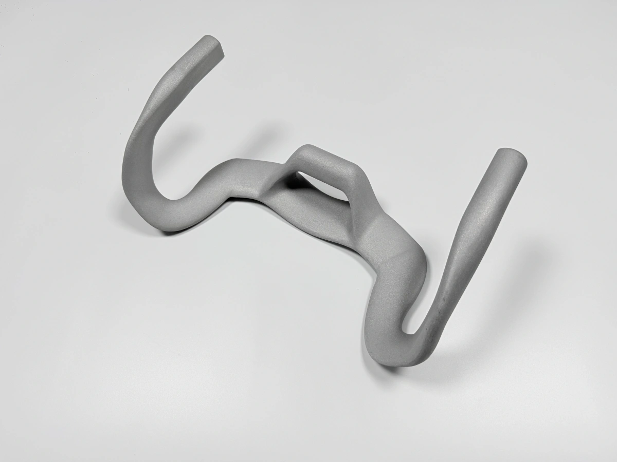
Hastelloy X is often reviewed for hot-gas hardware because buyers need a nickel-based superalloy option for oxidation-facing, thermally cycled, or combustion-adjacent components. In additive manufacturing RFQs, the material is usually paired with geometry that benefits from printing: curved ducts, thin-walled shields, integrated mounting tabs, short-run burner hardware, cooling or purge features, and test parts that may change after the first build.
The process is not automatically justified by temperature exposure. A simple ring, plate, spacer, or straight flange may be better served by machining or forming if stock and geometry allow it. AM becomes stronger when the part consolidates welded pieces, shortens a development loop, or contains internal features that would require several conventional operations. The buyer should describe the combustion or energy function before asking for a unit price.
Application words also need definition. "Combustion component" can mean a low-load liner coupon, a hot-gas duct, a sensor boss near a flame path, or a fixture for repeated thermal testing. Each one drives a different review of wall thickness, support access, surface finish, inspection, and thermal processing.
Thin Walls, Duct Turns, and Hot-Gas Faces Need Their Own DFM Review
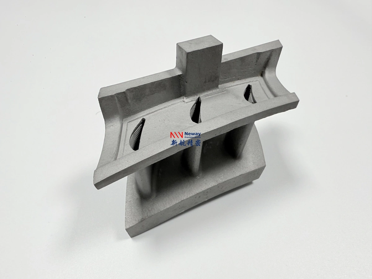
Thin walls are common in combustion liners and shields, but they are not only a printability question. Wall continuity, local thickness changes, unsupported lips, long slots, and sharp corner transitions can affect distortion and support scars. A wall that is acceptable for a static shield may be risky when it also carries assembly loads or when a sealing flange is attached to it.
Duct and manifold geometry should be reviewed for support removal and hot-side surface access. A curved outlet with an internal overhang may print, but the remaining support marks could disturb flow or block cleaning. If the surface is inside the gas path, the RFQ should identify whether light cleanup, local machining, abrasive finishing, borescope inspection, or CT review is expected. Without that information, two quotes may describe very different delivered states.
Holes and ports near hot faces need special attention. Sensor bosses, purge holes, threaded ports, and flange bolt holes usually need machining after printing and thermal processing. As-printed holes can help locate features, but the final diameter, thread, perpendicularity, and sealing condition should be defined on the drawing.
Combustion Part Type Changes the Quote Route
Combustion or energy part type | Main manufacturing concern | Operation that may drive quote | Acceptance evidence to define |
|---|---|---|---|
Thin combustion liner or heat shield | Wall distortion, edge stability, support marks on hot faces | Build orientation review, stress relief, local surface cleanup | Wall thickness zones, edge condition, hot-face visual standard |
Curved duct or exhaust guide | Internal flow surface and trapped support or powder | Support strategy, cleaning route, borescope or CT discussion | Accessible openings, flow path requirement, internal inspection method |
Burner or thermal test fixture | Thermal cycling, fixture interfaces, revision changes | Heat treatment, replaceable machined inserts, selected CMM report | Test stage, critical mounting datums, allowed design changes |
Sensor boss near hot gas | Thread quality, sealing, alignment to gas path | CNC drilling, tapping, spot facing after heat treatment | Thread standard, sealing face roughness, port location tolerance |
Coating-ready hot-side component | Surface preparation before TBC or oxidation-facing coating | Support removal, surface treatment, coating supplier interface | Coating zones, masked areas, pre-coating surface condition |
This table is useful because a Hastelloy X 3D printed part can be priced as a printed development item, a heat-treated blank, a machined assembly component, or a coating-ready hot-side part. The buyer should not compare prices unless the route category is the same.
Heat Treatment, HIP, and TBC Are Not the Same Decision
Heat treatment is usually discussed for residual stress, dimensional stability, or a required material condition. For thin combustion hardware, the sequence matters because a part may move after thermal processing. If a flange or port must be precise, machining may need to happen after heat treatment rather than before it.
HIP should be evaluated when the part has fatigue concern, pressure relevance, critical thermal cycling, or a customer acceptance requirement tied to internal defect reduction. It can be a required line item for some hot-section components, but an early burner fit-up part may only need optional HIP pricing. The RFQ should say whether HIP is mandatory, optional, or open for engineering recommendation.
Thermal barrier coatings belong to a different decision. TBC discussion depends on hot-side exposure, coating zones, surface preparation, and masking requirements. A coating-ready Hastelloy X part may need support marks removed from the coated face, controlled roughness on selected areas, and agreement about which surfaces should remain uncoated for assembly or grounding.
CNC and EDM Scope for Interfaces Near the Hot Zone
CNC machining should be named when the part has sealing faces, bolt patterns, threaded ports, flange datums, sensor seats, gasket lands, or mating faces. These features often control whether a combustion or energy component can be assembled and tested. Leaving them as printed may be acceptable only when the drawing gives a tolerance and roughness range that matches the function.
EDM or special machining may enter the discussion when a slot, notch, or hard-to-reach feature cannot be milled cleanly after printing. The buyer should mark whether a feature is a flow edge, a clearance relief, or an assembly datum. That distinction controls whether a local witness mark matters. For thin wall parts, fixture planning may be as important as cutting time because aggressive clamping can deform the shell.
Machining allowance should be included before the build. If the CAD model represents finished dimensions everywhere, Neway may need approval to add stock on flanges, pads, or ports. A coating-ready part may also need machining before coating and inspection after coating, depending on which surfaces are functional.
Inspection for Hot-Gas Parts Should Follow the Failure Mode
Inspection for Hastelloy X combustion parts should not be copied from a generic drawing note. A hot-gas duct may require internal cleanliness evidence, a liner may need wall thickness and edge review, and a sensor port may need thread and sealing inspection. A thermal fixture may need only selected CMM points on mounting faces if the hot-side surface is not a tight geometry feature.
For energy and power applications, acceptance may involve leak relevance, pressure exposure, thermal cycling, corrosion or oxidation exposure, and documentation for test records. Buyers should state which of these actually applies. Asking for every possible record increases cost and can slow a prototype that only needs design learning.
If internal channels or duct surfaces are present, standard external CMM inspection may not verify the important feature. Borescope review, CT discussion, sectioned witness coupons, flow-path cleaning evidence, or pressure/leak requirements may be considered depending on geometry and acceptance requirements. These checks should be specified before the quote is finalized.
RFQ Details Needed Before a Hastelloy X Hot-Gas Quote Is Reliable
For a reliable Hastelloy X 3D printing service quote, send the STEP file, 2D drawing, part revision, quantity, prototype or repeat production stage, hot-gas or energy application, temperature range if known, pressure or leak relevance, thermal cycling condition, critical wall thicknesses, machined faces, ports, threads, sealing surfaces, coating or TBC zones, heat treatment expectations, HIP requirement or optional pricing request, surface finish zones, inspection records, and target delivery need.
If the design is still flexible, mark which features can change for DFM. Useful options include adding drain or cleaning access, changing a sharp corner to a blended transition, adding machining stock to a port, relocating a support-sensitive face, or splitting a part when an internal surface cannot be cleaned or inspected. A quote becomes more comparable when it separates printed blank, thermally processed blank, machined part, and coating-ready part.
Related FAQs