TBC Masking and Machined Interfaces for AM Hot-Section Hardware
If a ceramic thermal barrier coating is added to an AM hot-section part without a clear masking plan, the problem usually appears at assembly, not during coating. Sealing lands, datums, bores, threads, cooling-hole exits, flange faces, and sensor interfaces may all need a no-coat boundary. For buyers, that boundary changes the quote because it decides whether masking, post-coating cleanup, CNC protection, or extra inspection is part of the finished scope.
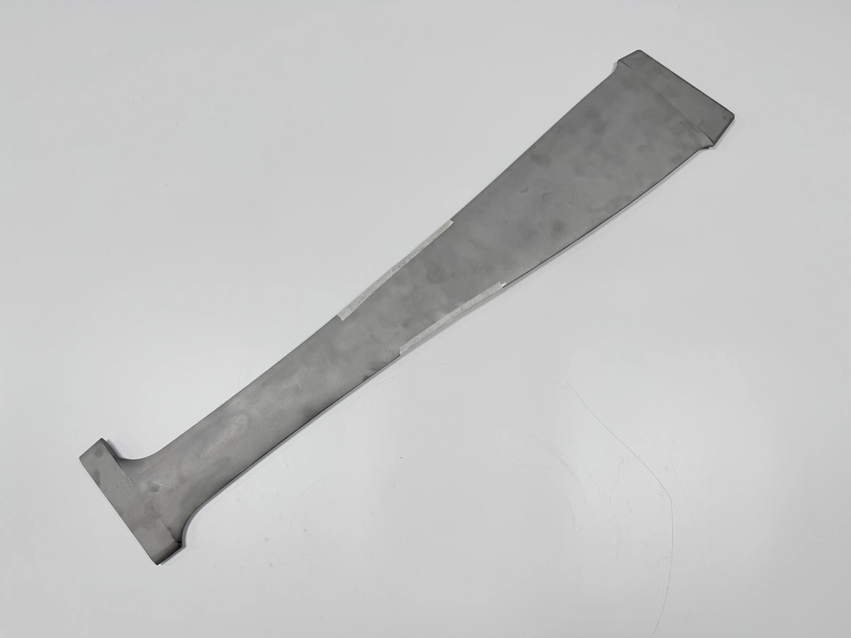
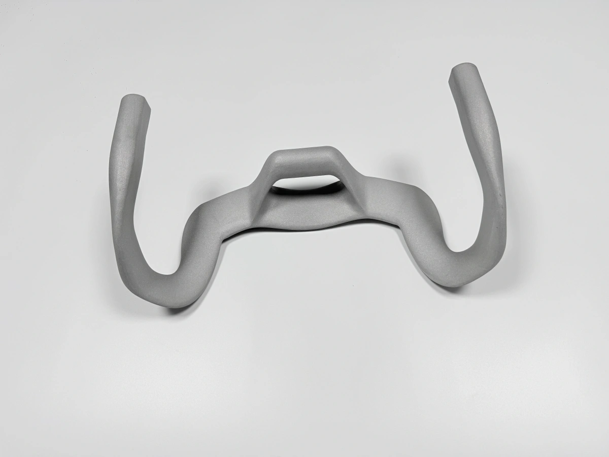
When Neway reviews a coated hot-section RFQ, we do not treat thermal barrier coating as a final cosmetic step. We check how the coating will interact with the printed surface, machined interfaces, temperature exposure, and acceptance drawing. A printed superalloy bracket, vane-related fixture, combustor-side insert, or Inconel 713C component may be printable, but it can still fail a purchase review if coated interfaces are not separated from functional interfaces.
This article is for engineers and purchasing teams preparing AM hardware that requires TBC after printing and machining. The practical decision is simple: define where coating is required, where coating is forbidden, and how each boundary will be inspected before the purchase order is released.
Why Sealing Faces Usually Need a No-Coat Boundary
Sealing faces are among the first features we isolate when reviewing thermal barrier coating scope. A ceramic coating layer may be useful on the hot gas side, but the same layer can interfere with metal-to-metal contact, gasket compression, clamp load, or a controlled leakage path. If the drawing only says "apply TBC all over," the buyer may receive a coating quote that is cheaper at first but incomplete for assembly.
For AM hot-section hardware, sealing faces are often created or refined after printing. The printed blank may be stress relieved, supports may be removed, and the sealing land may then be CNC machined to the drawing requirement. If that land is coated afterward, the finished geometry may no longer represent the machined condition. In many RFQs, the better route is to mark the sealing land as no-coat, protect it during spraying, and inspect the coating edge after masking removal.
We also look at whether the sealing surface sits next to a radius, rib, cooling edge, or step. A sharp coating stop line on a tight corner can be difficult to mask cleanly. A drawing-defined transition area may make the coated part easier to manufacture and inspect. That choice should be made before quotation because it affects masking labor and rework risk.
Datum Pads and Bores That Should Be Protected
Datum pads control how a finished AM part is measured, machined, and assembled. They should normally remain free of TBC unless the customer drawing specifically accepts a coated datum. A coated datum can create unstable CMM contact, change stack-up, or hide the real condition of the machined pad. For precision hot-section hardware, this is one of the clearest examples of a coating instruction affecting dimensional acceptance.
Bores and holes require the same discipline. A bore used for a dowel, pin, shaft, threaded insert, sensor sleeve, or fluid connector should be called out separately from surfaces that need temperature protection. If the bore is printed near-net and then CNC finished, the buyer should decide whether coating is excluded entirely, excluded only from the finished diameter, or allowed on nearby non-contact surfaces. If the coating reaches the bore wall, the part may need post-coating cleanup, which can add risk when tool access is limited.
Threaded holes are another common source of avoidable cost. Coating on internal threads can cause assembly problems, while masking small threaded features may be more practical if the thread is created after coating. For some geometries, the better plan is to leave printed pilot holes, apply TBC with defined protection, and machine or tap threads afterward. For other parts, completed threads must be protected because later machining access is not available. The quote should reflect that decision instead of treating all holes as identical.
How Coating Overspray Changes Assembly Clearance
Overspray is not only a surface appearance issue. It can change clearance near slots, narrow grooves, bolt counterbores, locating bosses, and mating flanges. On AM hardware, these features may already have build-orientation effects, support-removal marks, or local roughness. Adding coating without a boundary may close a clearance that was acceptable in CAD but tight in the finished assembly.
We pay particular attention to interfaces that combine AM geometry with a downstream machined surface. For example, a printed cooling structure may need TBC on the exposed thermal face, while an adjacent flange must remain metal for bolting. If the coated and uncoated areas are too close together, the buyer should expect a more detailed masking process or a drawing revision that gives the supplier a realistic transition zone.
Overspray also affects inspection. A visual check may confirm that coating exists, but it may not verify that a no-coat surface remains within an assembly envelope. For functional interfaces, the acceptance method should match the risk: CMM for datum pads and machined locations, go/no-go checks for fit features when appropriate, and visual boundary inspection for coating edges.
Feature | Coating status | Reason | Drawing callout | Inspection method |
|---|---|---|---|---|
Hot gas exposed wall | Coat as specified | Thermal protection is the main function of this surface | Identify coating zone and required edge boundary | Visual boundary check and coating record review |
Sealing land | No-coat unless drawing accepts coating | Coating can change contact, compression, or leakage behavior | Mark as masked or keep bare after final machining | CMM or drawing-based surface inspection |
Datum pad | Protect during coating | Measurement and fixturing need a stable metal reference | Define datum symbol and no-coat boundary | CMM after coating and mask removal |
Finished bore | Mask or machine after coating | Coating can reduce fit clearance or damage assembly | State final bore condition and machining stage | Plug gauge, CMM, or bore measurement by drawing need |
Threaded hole | Protect or cut after coating | Thread engagement should not depend on coated ceramic surface | Specify whether tapping occurs before or after coating | Thread gauge after final operation |
Thin rib edge | Review before coating release | Masking and coating buildup can chip at weak edges | Add edge condition or local relief if needed | Visual inspection with boundary note |
Drawing Notes That Make Masking Quotation Clear
A useful drawing note is not just "mask critical surfaces." It should tell the supplier which surfaces are coated, which are not coated, and which features are machined after coating. Buyers can reduce quote ambiguity by using color-marked PDFs, section views, or a coating zone table when the geometry is complex. STEP data gives the shape, but a 2D drawing usually carries the acceptance rules.
For superalloy 3D printing service projects, the coating plan should be consistent with the earlier AM and machining plan. If support contact occurs on a face that later receives TBC, the surface preparation requirement may be different from a machined sealing land. If a ceramic layer is applied near a CNC datum, the datum should not be lost under coating. If an Inconel 713C 3D printing service part has a hot-side profile and a cold-side mounting interface, those areas should not share one blanket coating note.
Another useful note is the order of operations. Some parts should be printed, stress relieved, machined on key interfaces, coated with masking, then inspected. Other parts may need coating before final light machining or EDM at a protected feature. The order depends on access and acceptance requirements, and it should be quoted as a defined route.
When Post-Coating Touch-Up Creates Acceptance Risk
Touch-up sounds minor, but it can become a separate acceptance issue when it affects a coating edge, a machined surface, or a thin AM feature. Removing ceramic overspray from a bore or sealing face after coating may be possible on an open surface, but it is less predictable inside a recess, near a delicate rib, or close to a complex cooling exit. If a buyer expects touch-up to be included, that expectation should appear in the RFQ.
We also separate cosmetic cleanup from functional cleanup. Cosmetic cleanup may only improve visible edges. Functional cleanup protects a fit, seal, measurement datum, or flow path. The second category has stronger drawing and inspection consequences. It may need CNC machining, light abrasive finishing, careful manual work, or a different masking plan. The quotation should not hide this difference in a general coating line.
Surface preparation before coating should also be treated carefully. The printed surface, support-removal zone, machined land, and blended transition do not behave the same way. A hot-side surface may need preparation suitable for ceramic coating adhesion, while a sealing land may need protection from that same preparation. This is why industrial part surface treatment planning should be connected to the AM build route and not left until the final shipping stage.
Information Needed Before Coating Scope Is Released
Before Neway can quote coated AM hot-section hardware with fewer assumptions, the buyer should provide the STEP file, 2D drawing, intended material grade, quantity, application environment, coated zones, no-coat zones, machined surfaces, datum scheme, thread and bore requirements, surface finish expectations, heat treatment or HIP expectations, and the inspection records needed for receiving. A marked PDF is helpful when the coating boundary is hard to explain with text alone.
The RFQ should also separate prototype learning from repeat purchase needs. A prototype may be used to confirm masking feasibility, coating boundaries, or assembly clearance. A repeat lot needs frozen drawing notes, stable no-coat definitions, and acceptance records that can be applied consistently. If a sealing face, bore, or datum is critical to function, it should be confirmed before PO release rather than corrected after the coating operation.
When the part is not a good candidate for ceramic coating after AM, we will say so during engineering review. Examples include inaccessible internal features where overspray cannot be controlled, thin edges that may be damaged by masking or cleanup, interfaces with no realistic no-coat boundary, and simple hot-section brackets where conventional machining and coating may be more practical than additive manufacturing. The goal is not to coat every printed surface; it is to deliver a finished part whose coating, machining, and inspection scope match the way the assembly will be used.
Related FAQs
What is the primary benefit of thermal barrier coatings for 3D printed parts?
What challenges are associated with the application of TBC coatings?
How do TBCs reduce thermal stress in high-temperature environments?
What are the challenges of applying and maintaining thermal barrier coatings?
Which materials benefit most from TBC for oxidation and corrosion resistance?