Can TBC cover complex shapes effectively?
Can TBC cover complex shapes effectively?
A TBC can cover many external curves, ribs, bosses, and heat-shield surfaces, but effective coverage of a complex 3D-printed shape must be demonstrated feature by feature. Air plasma spray (APS) and electron beam physical vapor deposition (EB-PVD) are strongly influenced by line of sight, spray angle, stand-off, part rotation, masking, and local thermal history. A nominal coating thickness on a flat witness coupon does not prove uniform coverage on an undercut, narrow channel, lattice, or sharp edge. The acceptance question is whether the critical surface has the required coating continuity, thickness, adhesion, and functional clearance in the final state.
Access and Deposition Geometry
The TBC coverage mechanism depends on line-of-sight access, spray angle, stand-off, part rotation, and local cooling during deposition. External convex surfaces are generally easier to reach than internal or recessed surfaces. A robotic multi-axis fixture can change the angle and distance during APS, while rotation or oscillation can reduce directional build-up. EB-PVD can create a strain-tolerant columnar structure, but its vapor path remains directional. Suspension plasma spray or solution precursor routes may address finer features in some systems, yet precursor flow, drying, chemistry, overspray, and inspection need their own qualification.
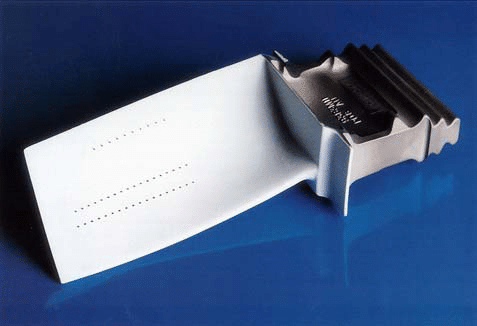
The printed-surface mechanism is controlled by texture, partially fused particles, support marks, open pores, and thin walls because those conditions alter cleaning, roughness, local heat transfer, and coating thickness. A powder bed fusion part may need controlled surface preparation and machining of critical datums before deposition. For a printed turbine vane, choose a robotic TBC route only when leading-edge and cooling-hole coverage is mapped; verify thickness, adhesion, flow, erosion, and final geometry. For a lattice heat shield, select the route only when access and cleaning are demonstrated on representative cells; verify mass, coverage, thermal response, and hidden-region limitations.
Thickness, Edges, and Masking
Complex shapes fail when a local thickness difference changes thermal resistance or interface strain. Thin coverage may not meet the thermal target, while a thick ridge at an edge can spall or interfere with a seal. Mask cooling holes, threads, datums, and sliding surfaces according to the drawing. Measure the coating at flats, radii, leading and trailing edges, recesses, and the boundary of every masked feature. Record gauge type, calibration, location, and uncertainty. If a feature cannot accept a direct measurement, use a validated witness or complementary method and state the limitation.
Surface preparation must preserve geometry. Aggressive blasting can round an edge, close a small hole, embed media, or remove a thin wall margin. Cleaning and activation should be selected for the alloy and bond coat. A coating should not be applied over a surface-connected crack or contamination because the layer may conceal the defect without restoring the load path. Superalloy printing, titanium printing, and ceramic printing have different substrate and access boundaries.
Hidden Surfaces and Inspection
The inspection mechanism depends on whether internal cooling passages, blind recesses, and lattice intersections can be reached and measured. CT, radiography, borescope, flow, leak, dye, or other methods may be appropriate, but each method has a resolution and geometry limit. A cross-section can confirm a local interface but is destructive. A flow test can show a blocked passage but cannot by itself prove coating thickness. Combine the process record with the evidence that measures the actual risk.
For a printed exhaust manifold, select a TBC when heat and oxidation threaten an accessible outer wall and the internal passage remains functional; verify coating loss, vibration, leakage or flow, and seal clearance after cycling. For a printed chemical hot-fluid component, select it only if pressure, fluid chemistry, cleaning, and hidden-surface continuity are within the test; verify pressure, flow, corrosion, and post-test inspection. These are separate buyer scenarios with different acceptance signals.
Decision and RFQ Requirements
Provide CAD and drawing revision, alloy and lot, additive route, build orientation, wall thickness, critical radii, channels or lattice dimensions, masking areas, surface condition, heat-treatment or HIP history, service temperatures, heat flux, cooling, gas or fluid chemistry, pressure, vibration, coating architecture, thickness range, inspection access, quantity, and approval authority. Request a tool-path or fixture record, deposition parameters, witness data, thickness map, adhesion evidence, cross-sections or NDT, flow or leak testing, dimensional report, and deviations.
Use a TBC on a complex shape only when the required surface is reachable and the measurement method can resolve the critical feature. If complete internal coverage is not feasible, consider a material or assembly route that removes the need for a post-applied barrier on that surface, such as a suitable ceramic 3D printing design. Record the uncoated region rather than implying full coverage, and release only the final state supported by the demonstrated evidence.
Before approving this application route, check the thermal barrier coating service against the part's operating condition, critical feature, and acceptance limit.
For supplier comparison, use the surface-treatment service to separate a process capability statement from evidence on the completed part.