TBC Enhanced Heat Resistance: Maximizing Temperature Endurance for 3D Parts
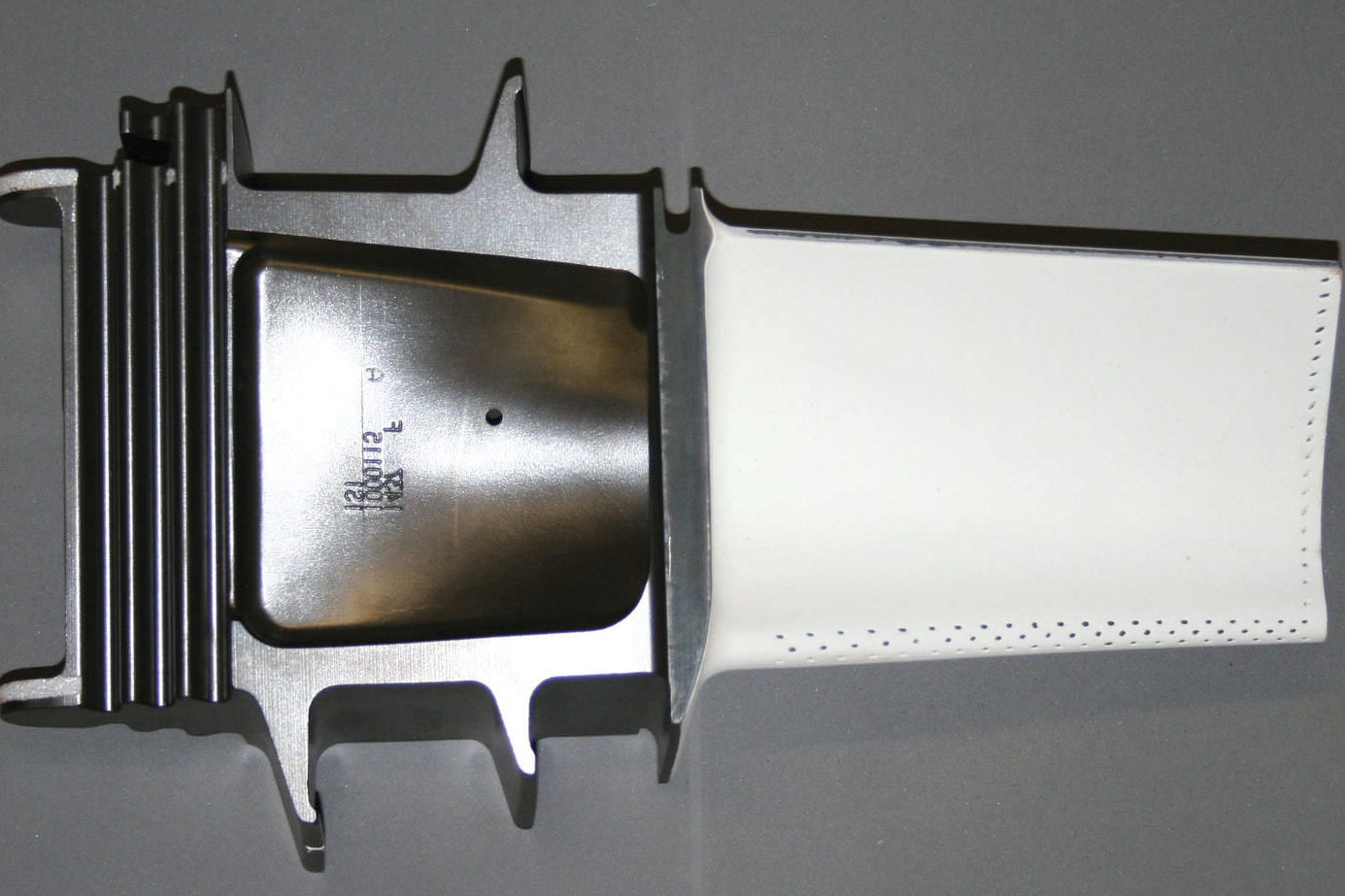 Thermal Barrier Coatings (TBCs) have become essential for protecting 3D printed parts exposed to extreme heat in aerospace, power generation, and automotive industries. TBCs are designed to provide enhanced heat resistance, allowing components to endure high temperatures without undergoing damage or failure. By maximizing temperature endurance, TBCs extend the lifespan of critical parts, improve system performance, and reduce maintenance costs. This article explores how TBCs enhance heat resistance for 3D printed parts and their benefits across industries.
What Are Thermal Barrier Coatings (TBCs)?
Thermal Barrier Coatings (TBCs) are protective layers applied to metal or ceramic substrates to prevent heat from penetrating and causing damage. These coatings act as insulation, reducing the temperature experienced by the underlying material, which helps parts withstand extreme heat in demanding environments. TBCs are often made from high-temperature resistant ceramics like zirconia (YSZ) and alumina, known for their excellent insulating properties.
TBCs are typically applied using advanced coating methods such as:
Plasma Spraying: A high-energy process that uses plasma to melt and spray ceramic material onto the part.
Electron Beam Physical Vapor Deposition (EB-PVD): A precise method that uses electron beams to evaporate ceramic material, which is then deposited onto the part’s surface in a vacuum.
These methods ensure that TBCs provide a uniform layer of insulation, optimizing temperature control and enhancing part durability.
How TBCs Maximize Temperature Endurance for 3D Parts
TBCs improve the heat resistance of 3D printed parts by providing the following benefits:
Thermal Insulation: The primary function of TBCs is to insulate parts from high temperatures. Materials such as zirconia (YSZ) have a low thermal conductivity, allowing them to withstand temperatures as high as 1500°C without transferring excessive heat to the underlying material. This insulation enables 3D printed parts to operate in high-temperature environments without degradation.
Thermal Cycling Protection: 3D printed parts often undergo thermal cycling, rapidly heated and cooled during operation. This can cause thermal stress, leading to cracks and part failure. TBCs help reduce the thermal stress by absorbing and dissipating heat, preventing the substrate material from expanding and contracting too quickly. This is particularly important in applications like gas turbines and jet engines, where parts are exposed to constant thermal fluctuations.
Corrosion and Oxidation Resistance: TBCs prevent oxidation and corrosion at high temperatures, besides thermal protection. By creating a barrier between the substrate and harsh environmental conditions (such as high-temperature gases in turbines), TBCs reduce the rate of material degradation. This is especially critical for components exposed to aggressive environments in aerospace, power generation, and chemical processing industries.
Improved Part Lifespan: By minimizing heat-induced damage, TBCs enhance the durability of 3D printed parts. Components such as turbine blades, exhaust systems, and engine components benefit from extended service life and fewer repairs, which lowers operational costs and downtime.
Applications of TBCs in 3D Printing
TBCs are used to enhance the performance of 3D printed parts across various industries. Below is a table highlighting key applications and the corresponding benefits:
Industry | Applications | Benefits |
|---|---|---|
Aerospace | Turbine blades, combustor liners, nozzle guide vanes | Improved efficiency, reduced fuel consumption, enhanced part life |
Power Generation | Gas turbine blades, heat exchangers | Higher temperature endurance, increased system efficiency |
Automotive | Engine components, exhaust systems, turbochargers | Enhanced heat resistance, improved engine performance |
Marine | Gas turbines, propulsion systems | Prolonged durability in harsh marine environments |
Chemical | Reactors, valves, pumps | Increased resistance to high-temperature wear and corrosion |
Benefits of TBCs in Maximizing Heat Endurance
Extended Part Life: TBCs reduce thermal stress and oxidation, allowing parts to last longer under high-temperature conditions. This is especially beneficial for parts exposed to extreme temperatures for extended periods, such as in aerospace and energy industries.
Increased Performance: By enabling parts to operate at higher temperatures, TBCs improve overall system efficiency. For example, in gas turbines, TBCs allow turbines to operate at higher combustion temperatures, leading to more efficient energy production.
Reduced Maintenance and Downtime: With improved heat resistance, TBC-coated parts experience less wear and tear, reducing the need for frequent maintenance. This leads to cost savings and increased uptime in industries where reliability is critical.
Cost-Effective: Although applying TBCs adds cost, the benefits of longer-lasting, higher-performing parts often outweigh the initial expense. The cost savings from reduced maintenance and repairs make TBCs a cost-effective investment in the long run.
Challenges of TBC Application
While TBCs offer significant benefits, there are challenges to their application:
Coating Durability: Over time, TBCs can degrade due to thermal cycling, mechanical wear, and exposure to harsh environmental conditions. Advances in coating materials and application techniques are focused on improving the longevity and durability of TBCs.
Application Complexity: The process of applying TBCs requires specialized equipment and expertise. Coating methods like EB-PVD and plasma spraying require precise control to ensure the coating is uniform and adheres effectively to the substrate.
Adhesion Strength: The bond between the TBC and the underlying substrate must be strong enough to withstand the stresses imposed by thermal expansion and contraction. Proper adhesion is crucial to ensure the coating remains intact during the part’s operation.
Conclusion
Thermal Barrier Coatings (TBCs) are a critical technology for maximizing the temperature endurance and heat resistance of 3D printed parts. By providing insulation, preventing oxidation, and reducing thermal stress, TBCs enhance the performance, durability, and lifespan of parts used in aerospace, power generation, and automotive industries. As material science and coating technologies continue to advance, TBCs will play an even more pivotal role in enabling high-performance applications that operate in extreme heat environments.
FAQs
What is the primary benefit of Thermal Barrier Coatings (TBCs) for 3D printed parts?
How do TBCs enhance the performance of parts in high-temperature environments?
What industries benefit from the application of TBCs on 3D printed parts?
What challenges are associated with the application of TBC coatings?
How do TBC coatings improve the durability and lifespan of 3D printed parts?