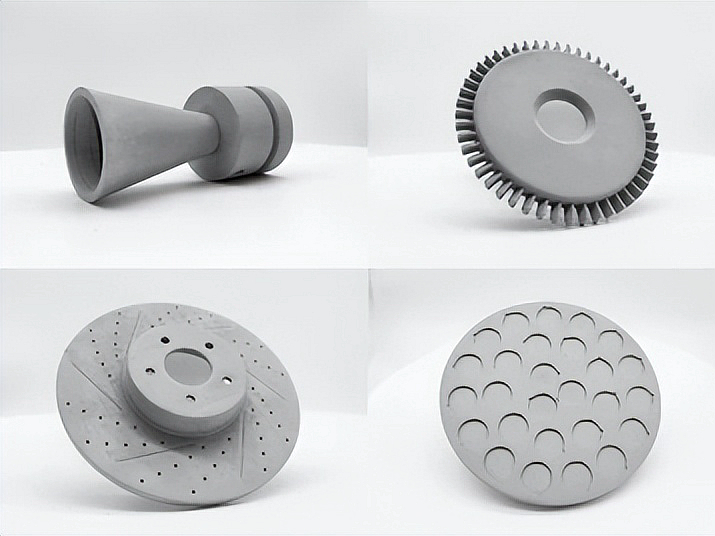
Innovative Applications of Ceramic in Custom 3D Printing From Art to AerospaceCeramic 3D printing is useful across art, electronics, tooling, medical development, energy, and aerospace only when the material, green-body route, firing schedule, and final failure mode are considered together. Alumina, zirconia, silica, silicon nitride, and silicon carbide have different thermal, electrical, chemical, and fracture behavior. Most slurry, paste, or powder routes create a green body first; debinding and sintering or firing then determine shrinkage, density, porosity, strength, and final dimensions. This article maps those states to practical applications without treating a printed shape as a finished ceramic part.
The central engineering mechanism is the conversion of a particle-filled feedstock into a fired ceramic. Binder content, particle packing, layer bonding, section thickness, furnace atmosphere, heating rate, support, and cooling rate govern whether the body densifies uniformly or develops distortion and cracks. A beautiful green model can fail during debinding, and a dimensionally accurate fired part can still fail from a tensile surface flaw. Application value therefore depends on a measured final state, not on resolution alone.
Material | Useful property to screen | Boundary to resolve | Evidence to request |
|---|---|---|---|
Alumina | Electrical insulation, chemical stability, and wear resistance | Thermal shock, porosity, surface flaw, dielectric condition, and fired density | Grade, firing record, density or porosity test, dielectric or flexural test, and dimensions |
Zirconia | High wear resistance and selected fracture-toughness behavior | Phase composition, aging environment, thermal cycling, surface, and stabilizer | Powder or slurry lot, firing condition, phase or density result, strength, and surface report |
Silica | Selected thermal, investment, or artistic applications with a defined furnace boundary | Thermal expansion, moisture, vitrification, strength, and temperature exposure | Feedstock condition, firing profile, dimensional result, and thermal test |
Silicon nitride | Thermal-shock tolerance and mechanical performance in selected applications | Porosity, additives, atmosphere, surface flaw, fracture, and thermal cycling | Material specification, sintering route, density, flexural or fracture test, and inspection |
Silicon carbide | High-temperature, wear, and chemical-environment screening | Oxidation, joining, porosity, thermal gradient, and brittle fracture | Grade, firing or infiltration route, density, oxidation or thermal-cycle result, and dimensions |
The material table is a screening tool, not an application approval. Select alumina for an electrical insulator when dielectric strength, creepage geometry, fired density, and thermal cycling are specified. Select zirconia for a wear component when stabilizer, surface finish, moisture exposure, and fracture requirement are known. Consider silicon nitride or silicon carbide for thermal shock or high-temperature service only when atmosphere, temperature cycle, stress, and flaw sensitivity are tested. A material's bulk datasheet does not qualify a custom fired geometry.
Vat photopolymerization uses a ceramic-filled photosensitive slurry cured by SLA or DLP. It can capture fine detail in the green body, but resin burnout, debinding, support contact, particle loading, and sintering control the final ceramic. The green body is fragile, and a cure gradient or trapped binder can create cracks during the thermal cycle. Use this route when detail and small or medium geometry justify the controlled debinding and firing plan.
Material extrusion deposits a ceramic-filled filament, paste, or other feedstock. Bead width, viscosity, layer bonding, moisture, support, and drying affect the green body before debinding. It can suit larger or simpler forms, prototypes, artistic work, and selected technical parts, but surface texture and anisotropic green strength must be considered. Binder jetting deposits binder into a ceramic powder bed and also creates a fragile green body; packing, debinding, sintering, and shrinkage uniformity control the fired part.
Laser powder-bed routes for ceramics are generally more restricted because high melting temperature, low thermal conductivity, and thermal expansion differences can create severe thermal gradients. Material jetting or other specialized deposition routes may be available for patterns or supplier-specific ceramic feedstocks, but the buyer should confirm whether the delivered state is a fired structural ceramic and request route-specific evidence. Process names do not replace the green-body, debinding, and firing record.
Route | When to screen it | Main process mechanism | Final-state verification |
|---|---|---|---|
Ceramic SLA / DLP | Fine details, thin features, dental or technical prototypes, and controlled small parts | Light cures a particle-filled slurry before debinding and sintering | Green density, furnace record, fired shrinkage, density, porosity, dimensions, and strength |
Binder jetting | Suitable batch geometries and powder-fed ceramic production | Binder joins powder in a green body before debinding and sintering | Powder and binder lot, furnace profile, density, porosity, dimensions, and fracture-sensitive inspection |
Material extrusion | Large or simpler forms, prototypes, paste work, and selected artistic parts | Bead or paste deposition builds a green body with directional bonding | Drying record, debinding profile, fired shrinkage, density, surface, and dimensions |
Specialized powder or jetting route | Supplier-qualified patterns or research geometries | Route-specific deposition followed by a defined ceramic conversion | Conversion record, final composition, density, porosity, thermal response, and inspection |
The green body contains ceramic particles held by resin, binder, or paste. It has enough shape stability for handling only within a defined condition, and its strength is not the strength of the final ceramic. Debinding removes organic material through a controlled thermal or chemical sequence. If heating is too fast, gases can build pressure inside a low-permeability section and create cracks or blisters. If particle packing varies, different regions shrink at different rates.
Sintering or firing develops neck growth, density, phase condition, and final dimensions. Shrinkage depends on solids loading, packing, section thickness, furnace profile, support, and geometry, so a single compensation factor may not cover every feature. Record the green-body condition, debinding schedule, peak temperature, atmosphere, support, cooling profile, and final measurement. Use a representative geometry when dimensional or density acceptance matters.
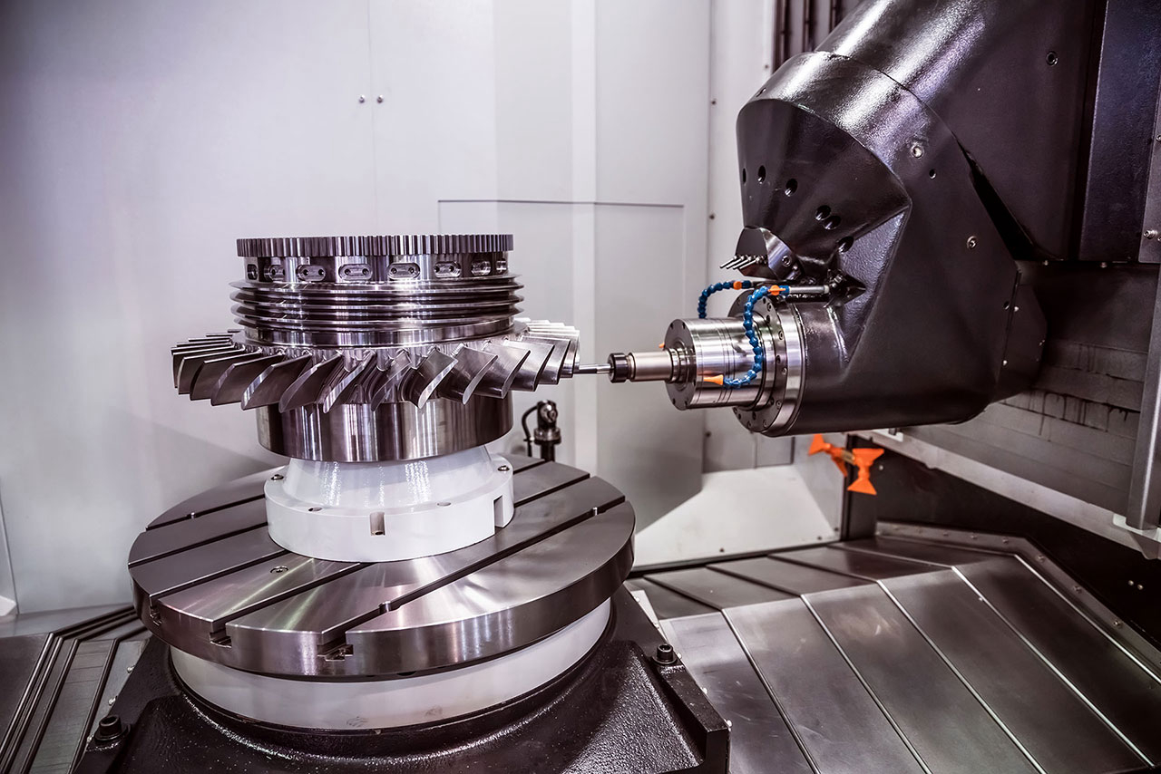
Post-processing may include machining, grinding, polishing, infiltration, glazing, or surface treatment. These steps can remove flaws or establish a sealing face, but they can also introduce edge damage, residual stress, contamination, or a new roughness condition. Inspect after the last operation that changes the critical surface. For a pressure or electrical application, test the final treated state rather than the unfired body.
Application | Why ceramic printing is screened | Primary risk | Verification focus |
|---|---|---|---|
Art and design | Custom form, hollow geometry, texture, and one-off production | Green-body handling, firing distortion, surface flaws, and finish consistency | Fired dimensions, surface inspection, color or glaze condition, and visual acceptance |
Electronics | Insulators, sensor forms, dielectric structures, and thermal isolation | Porosity, dielectric path, contamination, thermal cycling, and dimensional fit | Density, dielectric or insulation test, thermal cycle, surface, and assembly fit |
Medical development | Patient-specific models, selected guides, dental forms, or research structures | Material classification, cleaning, sterilization, surface, and regulatory boundary | Project qualification, fired dimensions, surface, chemistry, cleaning, and applicable tests |
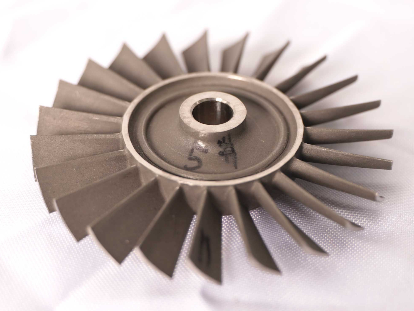
Aerospace and energy | Heat shields, insulators, nozzles, thermal-management forms, and high-temperature fixtures | Thermal shock, oxidation, fracture, porosity, pressure, and inspection access | Density, porosity, thermal cycle, oxidation, pressure or flow, fracture, and final dimensions |
Tooling and wear parts | Hard surfaces, chemical resistance, selected inserts, and custom channels | Impact fracture, edge chipping, thermal gradients, and tool-life uncertainty | Hardness or wear, thermal cycling, fit, edge inspection, and life test |
Debinding cracks: control particle loading, section thickness, heating rate, venting, and atmosphere only when the feedstock and geometry are characterized; inspect the debound body before firing when the geometry is fragile.
Sintering distortion: control packing, support, compensation, furnace profile, and cooling only when representative geometry is used; measure fired datums and shrinkage in more than one axis.
Porosity and density variation: control feedstock mixing, powder packing, slurry viscosity, and binder distribution only when the lot and loading are recorded; test apparent density or porosity with a named method such as ASTM C373 where applicable.
Brittle fracture and thermal shock: control corners, surface flaws, wall transitions, thermal gradient, and cooling rate only when the service cycle is defined; use flexural, fracture, or thermal-cycle evidence matched to the material and application.
Use ISO/ASTM 52900 for additive-manufacturing terminology, then apply the relevant ceramic material or product specification. ASTM C1161 may support flexural-strength testing for advanced ceramics, and ASTM C373 may support density or apparent-porosity measurements when their scope and specimen condition fit the project. Standards organize a test; they do not set a universal acceptance value for every printed alumina, zirconia, silica, silicon nitride, or silicon carbide geometry.
For an RFQ, provide CAD and drawing revision, ceramic material and grade, feedstock type and lot, solids loading or powder condition, process route, green-body handling, shrinkage allowance, fired dimensions, density or porosity, thermal cycle, atmosphere, load, temperature, fluid, pressure, electrical requirement, surface, cleaning or sterilization, inspection access, schedule, quantity, and approval authority. Request slurry or powder records, SLA/DLP or extrusion or binder-jet parameters, debinding and sintering/firing logs, dimensional report, density and porosity result, surface inspection, flexural or fracture method, thermal-cycle or pressure test, deviations, and final disposition.
For an aerospace insulator, nozzle, or thermal-management component, choose alumina, silicon nitride, silicon carbide, or another qualified ceramic only when the temperature, atmosphere, thermal shock, stress state, porosity, and fracture inspection are defined; verify the fired final state, not the green body. For an electronics insulator, choose alumina or another ceramic when dielectric path, contamination, fit, thermal cycling, and surface condition are specified; verify insulation and assembly after firing and finishing. For a medical or dental development part, choose zirconia, alumina, hydroxyapatite, or another material only when classification, cleaning, sterilization, biological, and regulatory requirements are covered by project-specific qualification; verify the final surface and dimensions. For an art or tooling part, choose SLA/DLP, binder jetting, or material extrusion from detail, batch size, green handling, glaze or surface, wear, and fired-shrinkage requirements; verify appearance or tool function in the final condition.
These application examples are decision boundaries, not universal approvals. Release a ceramic part only when material, route, green-body handling, debinding, firing, post-processing, inspection, and functional evidence describe the actual delivered state. If a critical feature cannot be measured, cleaned, or tested after firing, revise the geometry or route before production approval.
What Are the Main Advantages of Ceramic 3D Printing Compared to Traditional Methods?
How Does Ceramic 3D Printing Benefit Industries Like Aerospace and Medical?
What Are the Most Common 3D Printing Technologies for Ceramics?
How Do Ceramics Perform in High-Temperature and High-Stress Applications?
What Are the Challenges of Ceramic 3D Printing, and How Are They Addressed?