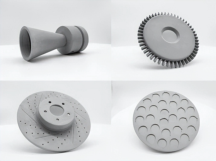
What are the challenges of ceramic 3D printing, and how are they addressed?
What are the challenges of ceramic 3D printing, and how are they addressed?
The short answer is that the main challenges can be addressed, but only with a route-specific control plan: fragile green bodies, binder removal, shrinkage, warpage, density variation, porosity, brittle fracture, surface roughness, thermal shock, and limited inspection access must be treated separately. Alumina, zirconia, silica, silicon nitride, and silicon carbide each have different feedstock and firing responses. SLA, DLP, binder jetting, and material extrusion also create different green-body mechanisms. Address a challenge by identifying the process variable, the failure mode, the final material state, the inspection method, and the acceptance criterion.
Feedstock and Green-Body Stability
Slurry viscosity, particle loading, sedimentation, powder size, binder saturation, bead width, moisture, and drying control the green body only when the feedstock lot and handling condition are recorded. A low solids loading may increase shrinkage, while poor mixing or packing can create density gradients. A green part can deform under support removal or handling even when the digital model is correct. Control powder or slurry lot, storage, mixing, viscosity, layer or bead parameters, support, drying, and handling when the geometry or acceptance plan requires repeatability. Inspect the green body before debinding when the geometry is delicate or the qualification plan requires it.
Debinding Cracks and Firing Shrinkage
Debinding removes organic material and must provide a path for gases to escape. Heating too quickly through a binder-removal interval can create internal pressure, cracking, or blisters. Sintering or firing then causes particle neck growth and shrinkage; section thickness, packing, support, atmosphere, peak temperature, and cooling control uniformity. For a zirconia or alumina component, choose a compensation and furnace route only after representative geometry is tested; measure shrinkage in more than one axis and inspect the debound and fired states.
Density, Porosity, and Dimensional Control
Density variation can come from slurry settling, powder packing, binder distribution, incomplete burnout, or local firing conditions. Open and closed porosity influence strength, leakage, dielectric behavior, thermal transfer, and cleaning. A fired dimension can be correct while an internal pore or crack remains unacceptable. Control solids loading or powder condition, furnace loading, support, thermal profile, and cooling when the geometry and furnace position are representative; verify density or apparent porosity, dimensions, internal features, and surface with methods appropriate to the material and geometry.
Brittleness, Surface, and Thermal Shock
Ceramics have limited plastic deformation, so corners, thin transitions, surface scratches, edge chips, pores, and debinding cracks can initiate fracture. Polishing or grinding may remove a flaw but can also create a new damaged layer or alter dimensions. Thermal shock depends on expansion, conductivity, strength, flaw population, wall thickness, and temperature change. For a silicon nitride, silicon carbide, alumina, or zirconia part, choose a rounded geometry and finishing sequence when the load and thermal cycle justify it; verify surface, fracture or flexural response, and thermal-cycle performance.
Qualification, High-Risk Use, and RFQ
For a medical, aerospace, pressure-boundary, electrical-insulation, or service-life claim, use project-specific qualification and documented acceptance criteria; a generic ceramic process description is not approval evidence. Control material, feedstock, SLA/DLP or binder-jet or extrusion route, green handling, debinding, firing, density, porosity, surface, dimensions, and inspection when those fields are part of the released specification. Hold the part if a critical feature cannot be cleaned, measured, or tested after firing.
Provide CAD and drawing revision, ceramic grade, feedstock lot, route, quantity, shrinkage allowance, fired dimensions, density, porosity, load, temperature, atmosphere, fluid, pressure, electrical requirement, surface, cleaning or sterilization, inspection access, schedule, and approval authority. Request print, drying, debinding, firing, density, dimensional, surface, flexural or fracture, thermal-cycle or pressure, deviation, and final-disposition records. Release the ceramic part only when the evidence supports its intended final condition.
For RFQ preparation, request the ceramic 3D printing service after the buyer defines the material state, quantity, and required verification method.
For final release, compare the vat photopolymerization service with the inspection record, service condition, and disposition of any unresolved risk.
.webp)