
EDM Tolerance Planning for AM Slots Holes and Thin Metal Features
EDM tolerance planning for AM slots, holes, and thin metal features should happen before the part is printed. A slot that looks clean in CAD may need a wire path, a start hole, a stable datum, and enough material for finishing. A thin wall may move after heat treatment. A small hole may be printable as a pilot feature but still need EDM, CNC, reaming, or redesign before acceptance.
Neway reviews EDM requests by separating the printed blank from the controlled feature. The additive process may create the near-net geometry, while electrical discharge machining protects sharp profiles, delicate features, and hard-to-cut zones where tool force or tool diameter is a concern. The quote becomes useful only when the drawing states which dimensions are EDM-controlled.
This article is for buyers sourcing precision metal additive manufacturing parts with slots, holes, thin ribs, sharp corners, or local surface finish requirements. It does not provide universal tolerance values; actual tolerance depends on the drawing, material, access, setup, thermal condition, electrode or wire route, and inspection method.
AM Slots That Should Be Reviewed for Wire or Sinker EDM
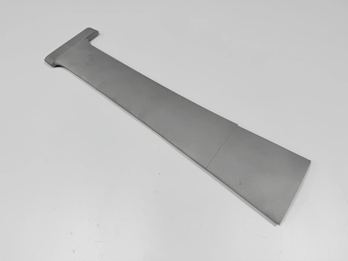
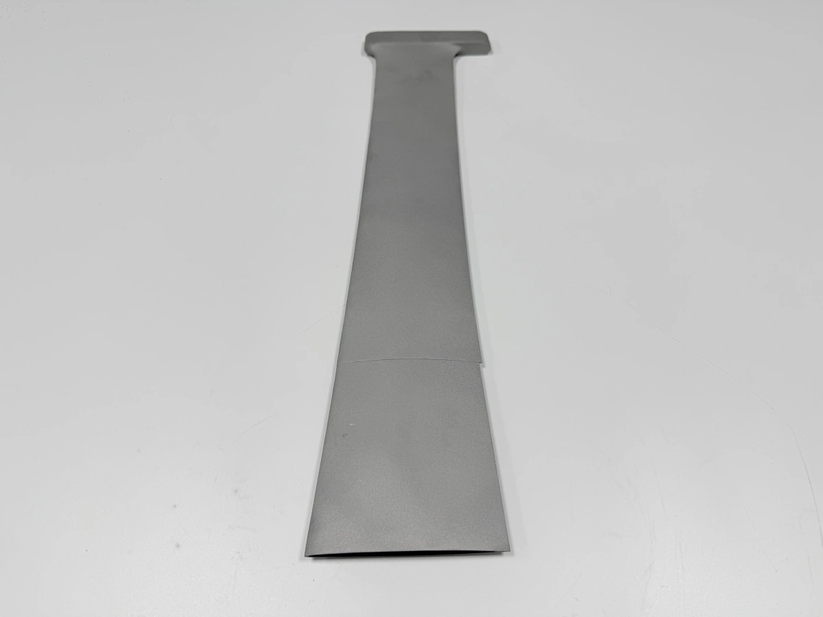
Narrow AM slots often create the first EDM question. If the slot is through-cut, wire EDM may be reviewed when a stable path, entry point, and fixturing strategy exist. If the feature is a blind cavity or shaped recess, sinker EDM may be discussed, but electrode access and flushing become important. A note saying "EDM slot" is not enough unless the access route is visible.
The buyer should mark whether the slot controls flow, assembly clearance, spring behavior, locating accuracy, or only weight reduction. A functional slot may need width, position, edge condition, and surface evidence. A clearance slot may be relaxed or redesigned for milling. Applying the same tolerance to every slot can add cost without improving the part.
Powder bed fusion can print slot-like openings, but support, powder removal, local texture, and thermal movement may still require finishing. If the slot lies behind a wall, under a rib, or inside an enclosed channel, EDM may not be reachable without a design change.
Small Holes and Sharp Corners After Metal Printing
Small holes should be classified before choosing the finishing route. A vent hole, drain hole, bolt clearance hole, dowel bore, and metering orifice have different acceptance needs. A printed pilot may be useful for location, but the final feature may need drilling, reaming, boring, EDM, or inspection depending on the material and access.
Sharp internal corners are another common EDM discussion. CNC cutters create radius limits, while EDM can be reviewed when a profile or corner must remain sharp according to the drawing. That does not mean EDM should be used everywhere. If a radius is acceptable, changing the corner can reduce finishing work and improve manufacturability.
Hole position also depends on datum quality. If a finished hole is referenced from an as-printed wall that moves during heat treatment, the tolerance may not be meaningful. A stable datum pad should be machined first when the final feature needs positional control.
Feature type | Why printing is insufficient | EDM access concern | Tolerance note | Inspection method |
|---|---|---|---|---|
Narrow through-slot | Printed edge texture and width variation may affect function | Wire path, start hole, fixture clearance, and part restraint | Define slot width, position, and edge condition only where functional | CMM, optical measurement, or gauge as specified |
Blind cavity or pocket detail | Milling access or cutter radius may not match the drawing | Electrode approach, flushing, and local debris removal | Separate profile tolerance from cosmetic surface notes | Profile inspection, visual evidence, or section-specific check |
Small precision hole | As-printed hole may not meet diameter, roundness, or edge needs | Access for electrode, rework path, and burr or recast control | State final diameter and whether printed pilot is allowed | Pin gauge, CMM, bore gauge, or buyer-defined method |
Thin rib beside EDM feature | Heat treatment or clamping can move the wall before finishing | Low-force setup and protection from handling damage | Do not over-control non-contact ribs if only clearance matters | Local thickness, profile, or visual edge review |
Sharp internal corner | CNC radius may exceed the allowed corner condition | Electrode shape, wear, and approach direction | Confirm whether a radius relief is acceptable | Optical check, profile measurement, or mating gauge |
Thin Features That Can Move Before EDM Finishing
Thin AM features may change shape during stress relief, heat treatment, support removal, or clamping. EDM is a low-force process compared with conventional cutting, but it cannot remove movement that already occurred. If a thin wall controls the final slot relationship, the sequence should protect that wall from distortion before the EDM setup begins.
Heat treatment should be considered before final EDM dimensions are assigned. A part may need stress relief before support removal, rough machining before EDM, or datum machining after thermal operations. The correct order depends on material, wall thickness, feature function, and acceptance requirements.
Machining tabs or sacrificial pads may help hold a thin printed part during finishing. Removing those tabs too early can make the EDM setup less stable. If the buyer wants tabs removed, the drawing should show which surfaces can be used for later fixturing and which surfaces must remain free of clamp marks.
Surface Finish Expectations That Change EDM Scope
EDM surface finish should be tied to a functional surface. A sliding contact face, sealing edge, precision profile, mold-like detail, or small flow feature may justify a defined EDM finish. A general note asking for improved finish on every printed wall can add work where the finish cannot be reached or does not affect function.
Surface condition after EDM may still require cleaning, polishing, deburring, or inspection depending on the drawing. Buyers should state whether the EDM surface is final or only an intermediate surface before additional finishing. If the part is made from a hard superalloy, titanium, stainless steel, or other difficult-to-cut metal, the finishing path should be reviewed with the material condition.
CNC machining and EDM often share the same part. CNC may create datums, pads, simple bores, and threaded holes. EDM may control narrow features, sharp profiles, or access-limited details. The RFQ should separate these features rather than applying one machining note to the entire part.
Drawing Notes That Separate CNC and EDM Tolerances
A useful drawing marks CNC-controlled dimensions and EDM-controlled dimensions separately. It should show datum references, critical-to-function dimensions, material condition before final finishing, and which features are measured after EDM. If a tolerance applies only to a slot, do not apply it to the whole printed body. If the feature must align with a machined pad, define the datum relationship.
It is also important to state when EDM is mandatory and when Neway may propose a design change. Enlarging a slot, adding a relief radius, opening an access path, or changing a blind feature to a through-feature can reduce EDM cost. The design team should decide whether those changes are allowed before purchasing compares quotes.
Blank allowance should be local rather than global. Extra stock near an EDM slot can protect the final edge, while excess material on unrelated walls may only increase build time, support removal, and handling work.
Inspection Evidence for EDM-Controlled AM Features
For a reliable EDM machining tolerances quote on printed metal parts, send the STEP file, 2D drawing, material grade, AM process if known, heat treatment condition, quantity, datum scheme, EDM-controlled features, required surface finish, access limits, and inspection records. Identify whether the part is a prototype, first article, or repeat lot. Mark slots, holes, sharp corners, thin walls, sealing features, and areas where EDM is optional.
Inspection evidence should match the feature. A slot may need width and position. A sharp corner may need optical or profile evidence. A thin feature may need local thickness or profile. An internal feature may need CT or a buyer-defined method if ordinary access is blocked. Defining these records before PO release helps Neway quote the operation that actually controls acceptance.
Related FAQs
.webp)
.webp)
