How does EDM machining improve the surface finish of 3D printed parts?
How does EDM machining improve the surface finish of 3D printed parts?
EDM can improve the surface condition of a conductive 3D-printed metal feature by replacing a high-energy roughing pass with one or more lower-energy finishing passes. Each discharge removes a small volume across a controlled gap, and stable dielectric flushing carries debris away. Smaller craters can produce lower measured roughness and more uniform reflectance, but the result depends on alloy, printed density, allowance, access, flushing, pulse energy, and final measurement. EDM does not polish by rubbing asperities away, and a lower Ra value does not by itself prove that recast or microcracks are acceptable. The EDM finishing route should be specified as a measured final condition.
Roughing and Finishing Passes
Roughing removes most of the machining allowance and usually uses more energy than a finishing pass. Higher current or longer pulse-on time can increase removal rate, but it may also create larger craters, deeper recast, and a wider heat-affected zone. A finishing pass uses a different parameter family to reduce the thermal event size. Its success requires enough remaining stock, stable gap control, clean dielectric, suitable flushing, and a tool path that does not overcut a corner or thin a wall.
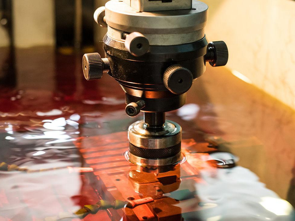
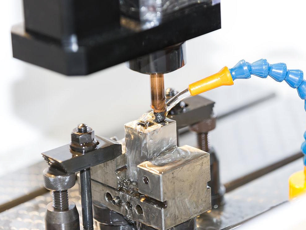
Wire EDM and sinker EDM create different textures. Wire EDM can finish an accessible through-profile, while sinker EDM transfers an electrode into a blind cavity. The wire, electrode, pass count, wear compensation, flushing direction, and feature depth must be recorded. A cavity floor can remain rougher than its opening if debris evacuation is poor. Inspect the locations that control friction, sealing, flow, fatigue, or cleaning instead of assigning one visual judgment to every surface.
Printed Material and Recast
The as-printed surface may contain partially fused particles, lack of fusion, gas porosity, support marks, and residual stress. EDM can expose these conditions or interact with them differently from wrought stock. The recast layer is resolidified material left by the discharge; its thickness, pores, phases, residual stress, and microcrack condition can matter even when the face looks bright. For a fatigue-sensitive part, define whether recast is removed, sectioned, or accepted under a project criterion. For a sealing surface, define pit, residue, and leak limits.
Workholding also affects the apparent finish. A flexible printed wall can be forced into alignment during EDM and spring back after unclamping. Establish datums after the specified stress-relief or heat-treatment state, support the part without overconstraint, and measure after release. If polishing, electropolishing, coating, or another surface treatment follows, record its allowance and inspect the final state again because a treatment can change roughness, reflectance, dimensions, or chemistry.
Surface Measurement and Failure Control
A lower roughness value can be useful only when the measurement direction, cutoff, location, and final cleaning condition are fixed. EDM may leave a recast layer, pitting, or microcracks even when the face looks bright, while polishing may remove stock or round a small edge. For a fatigue-sensitive aerospace insert, choose the finishing route only when recast evidence and an unclamped profile check are available. For a tooling cavity, verify floor, sidewall, corners, and final dimensions after any polishing or coating.
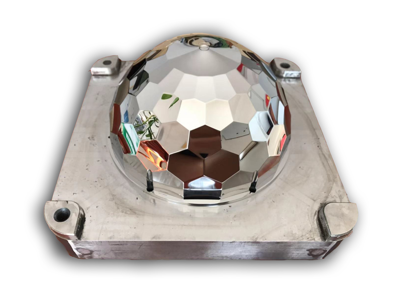
For a thin aerospace nozzle component, choose wire EDM when the profile is conductive and accessible and cutter force could deflect the wall; verify profile, roughness, recast, cleanliness, and flow or leak performance. For an automotive mold component, choose sinker EDM when the shaped electrode reaches the blind cavity; verify corner radius, cavity map, roughness, and final dimensions after polishing. The application decides whether texture, edge control, or surface integrity carries the highest risk.
Lower roughness can reduce friction or support cleaning only when the surface location, measurement direction, and final condition are specified and the measured result is compared with the functional requirement. Cleaning can preserve an internal surface only when dielectric and particles are removed and the result is verified. Polishing can change a critical edge only when the allowance is measured before and after the operation. A measured EDM result can support release only when the geometry, surface integrity, and application test agree with the drawing.
A finishing pass can reduce crater size only when pulse energy and flushing are stable. Stable dielectric flow can prevent local pitting only when debris evacuation is verified at the feature depth. A final measurement can support acceptance only when the part is unclamped, cleaned, and inspected against the drawing and surface-integrity requirement.
Application and Verification
For an aerospace cooling insert, choose EDM when the conductive contour is accessible and cutter force threatens a thin wall; verify roughness, profile, recast or HAZ, cleanliness, and flow or leak performance. For an automotive tooling cavity, choose sinker EDM when a shaped electrode reaches the feature; inspect the floor, sidewall, corner radius, roughness, and final dimensions after polishing. For a medical-development instrument, define the contact surface, cleaning, sterilization exposure, residue, and development approval boundary. A reflective appearance does not establish biocompatibility or clinical acceptance.
For a hardened mold insert with a deep blind pocket, choose sinker EDM when the electrode can reach the pocket and cutter force or tool wear would make milling unstable; verify electrode wear, floor depth, corner radius, recast condition, and cavity dimensions after unclamping. If the pocket cannot be flushed or inspected at depth, change the access design or use a different route before production approval.
Specify the roughness metric, measurement direction, cutoff and evaluation length when applicable, sample location, instrument, temperature, visual comparator, and final cleaning condition. Request baseline and final results, pass strategy, parameter family, dielectric record, dimensional map, surface-integrity evidence, and nonconformance disposition. If the requirement is unknown, run a representative trial and record the actual result before approving production. EDM improves surface finish only when the discharge process and the final evidence are controlled together.
For a primary route decision, use the electrical discharge machining edm after the material, geometry, and service condition for this question are defined.
For downstream verification, consult the CNC machining service when the final process state and acceptance evidence for this question must be recorded.