What is the most precise tolerance achievable with EDM machining?
What is the most precise tolerance achievable with EDM machining?
There is no single tolerance that every EDM machine can deliver on every 3D-printed part. The most precise achievable result is the tightest feature tolerance that a defined wire or sinker EDM route can repeatedly demonstrate on the specified conductive alloy, thickness, geometry, allowance, fixture, and final measurement method. A supplier may use a very small micron target during development, but that number should be treated as a project-specific capability claim until the actual part is measured after unclamping, cleaning, and any subsequent treatment. The EDM route should be quoted with evidence rather than a resolution number alone.
Tolerance Is Not Machine Resolution
Machine resolution is the smallest commanded movement or displayed increment. Accuracy is closeness to the nominal dimension. Repeatability is the spread of repeated results. Tolerance is the allowable variation on the drawing. These values are related but not interchangeable. A machine with sub-micron command resolution can still produce a feature outside a two-micron tolerance if thermal drift, spark gap, wire deflection, electrode wear, fixture distortion, residual stress, or measurement uncertainty is larger than the commanded step.
For a printed part, define the measurement state before discussing the smallest number. State the drawing revision, datum scheme, feature location, material lot, build orientation, heat-treatment state, and whether the part is measured in the fixture or after unclamping. Add inspection temperature, stabilization time, instrument type, calibration status, sample count, and measurement uncertainty. If the acceptance decision is close to the uncertainty, agree on a guard band or decision rule before production. ISO 230-2 may be used as a reference for machine-tool positioning evaluation, while ISO 14253-1 can help frame conformity decisions under measurement uncertainty; neither standard substitutes for a part-specific EDM study.
Wire and Sinker EDM Limits
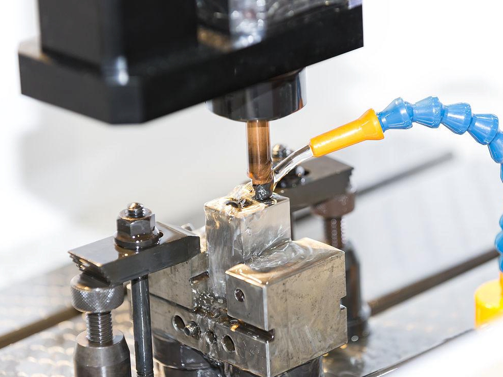
Wire EDM can be precise on an accessible through-profile because the wire follows a controlled path without continuous cutter contact. The effective result still includes wire tension, guide alignment, spark gap, taper, flushing, workpiece height, changing debris conditions, and the stiffness of the remaining section. A long thin contour can deflect or spring back after cutting. A start hole, wire entry, exit, and support plan must therefore be part of the tolerance review.
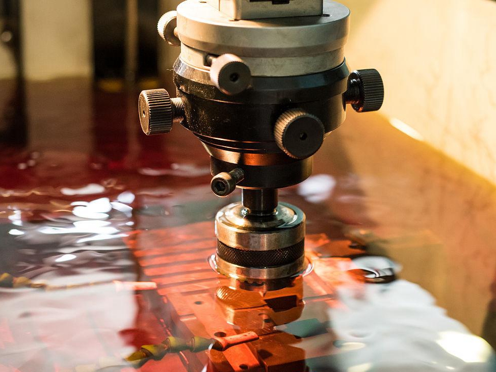
Sinker EDM transfers a shaped electrode into a blind cavity or local feature. Electrode form accuracy, wear compensation, orbiting, gap control, flushing direction, and corner access affect the result. The cavity floor may not match the sidewall because debris removal and thermal exposure differ. A deep narrow pocket can meet a size check at the opening and still fail its bottom radius, roughness, recast, or cleanliness requirement. Inspect the features that control function, not only the easiest face to reach.
How to Use a Precision Target
For many EDM RFQs, a target such as ±0.01 mm can be a reasonable starting point for discussion, while tighter values require a geometry-specific review. A ±0.002 mm target should be treated as a development or high-control requirement, not as a universal production promise. The relevant question is whether the supplier can show repeated measured results on the same alloy family, feature type, thickness, and final state. Ask how many parts or repeated features were measured, which dimensions were selected, and how outliers were handled.
Do not judge the target by a single polished sample. A finishing pass may reduce crater scale while leaving a recast layer, edge loss, or dimensional shift. A later surface-treatment step may remove stock or add coating thickness. Measure the as-EDM and final states separately, and record the operation responsible for each change. For a fatigue-sensitive feature, add recast or microcrack evidence; for a sealing surface, add leak testing under the specified pressure and temperature.
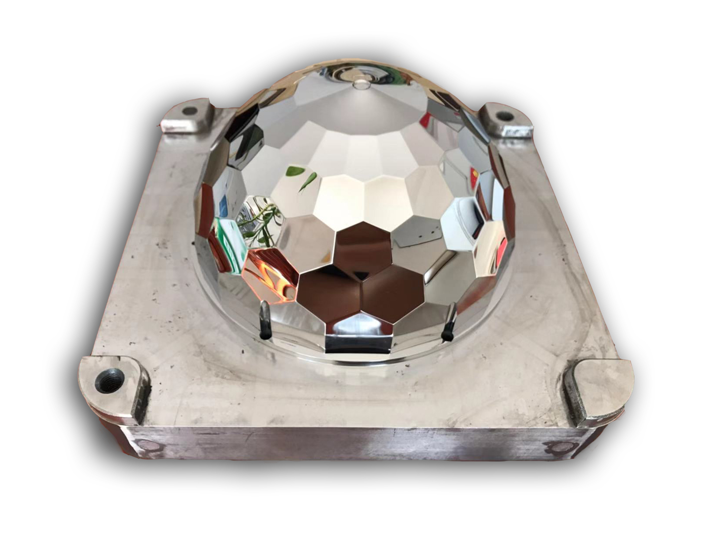
For a medical-development micro-feature component, choose a qualified EDM route when the conductive alloy and access permit a fine contour without cutter force; verify the feature after unclamping, cleaning, and any sterilization exposure used in development. For an automotive mold insert component, choose sinker EDM when the shaped electrode can reach the cavity and corner transfer controls function; verify the floor, sidewall, radius, roughness, and final dimensions. These are separate decisions because their measurement and service risks are different.
Buyer Verification and RFQ Fields
Give the buyer or supplier the CAD and drawing revision, tolerance by feature, material grade and lot, build orientation, heat-treatment condition, machining allowance, EDM mode, access restrictions, quantity, inspection method, and service requirement. Request the wire or electrode plan, parameter family, workholding datum, machine calibration status, temperature condition, CMM or optical report, roughness record, surface-integrity evidence, and nonconformance disposition. If a coupon is proposed, confirm that its thickness, orientation, material state, and access represent the component.
For an aerospace micro-nozzle, select wire EDM when the passage profile is accessible and low cutter force protects a thin or hard feature; verify profile, recast, cleanliness, and flow or leak performance after cleaning. For a tooling cavity, select sinker EDM when the electrode reaches the blind feature; verify floor, sidewall, corners, roughness, and final dimensions after polishing. In both cases, the most precise tolerance is the smallest one supported by repeated, traceable evidence on the final part, not a bare machine display value.
For a primary route decision, use the electrical discharge machining edm after the material, geometry, and service condition for this question are defined.
For downstream verification, consult the CNC machining service when the final process state and acceptance evidence for this question must be recorded.