CNC Post-Machining for 3D Printed Metal Parts and RFQs
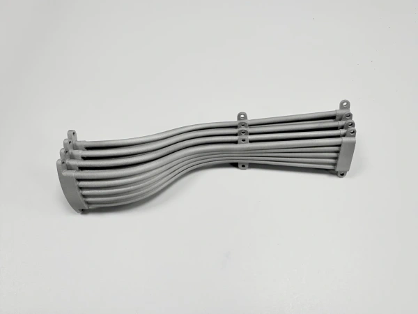
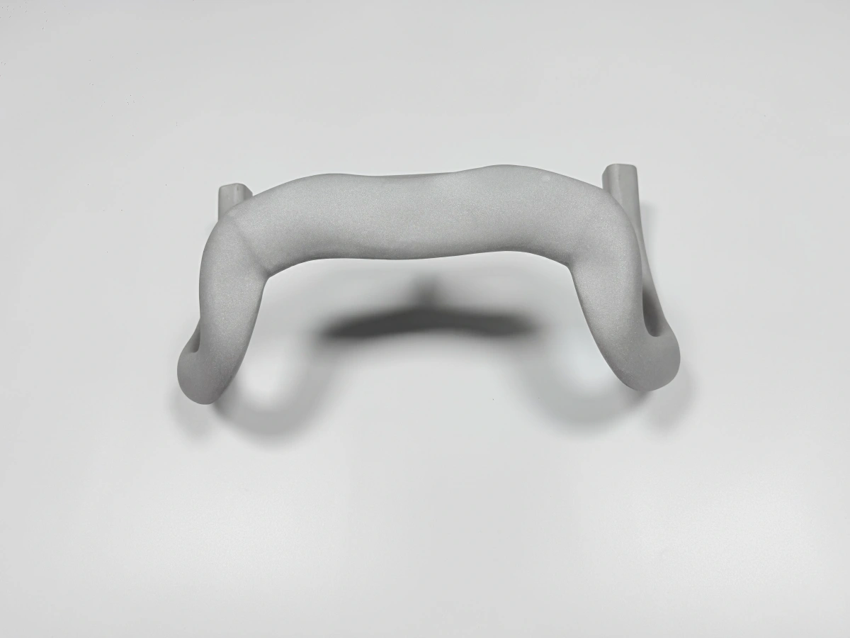
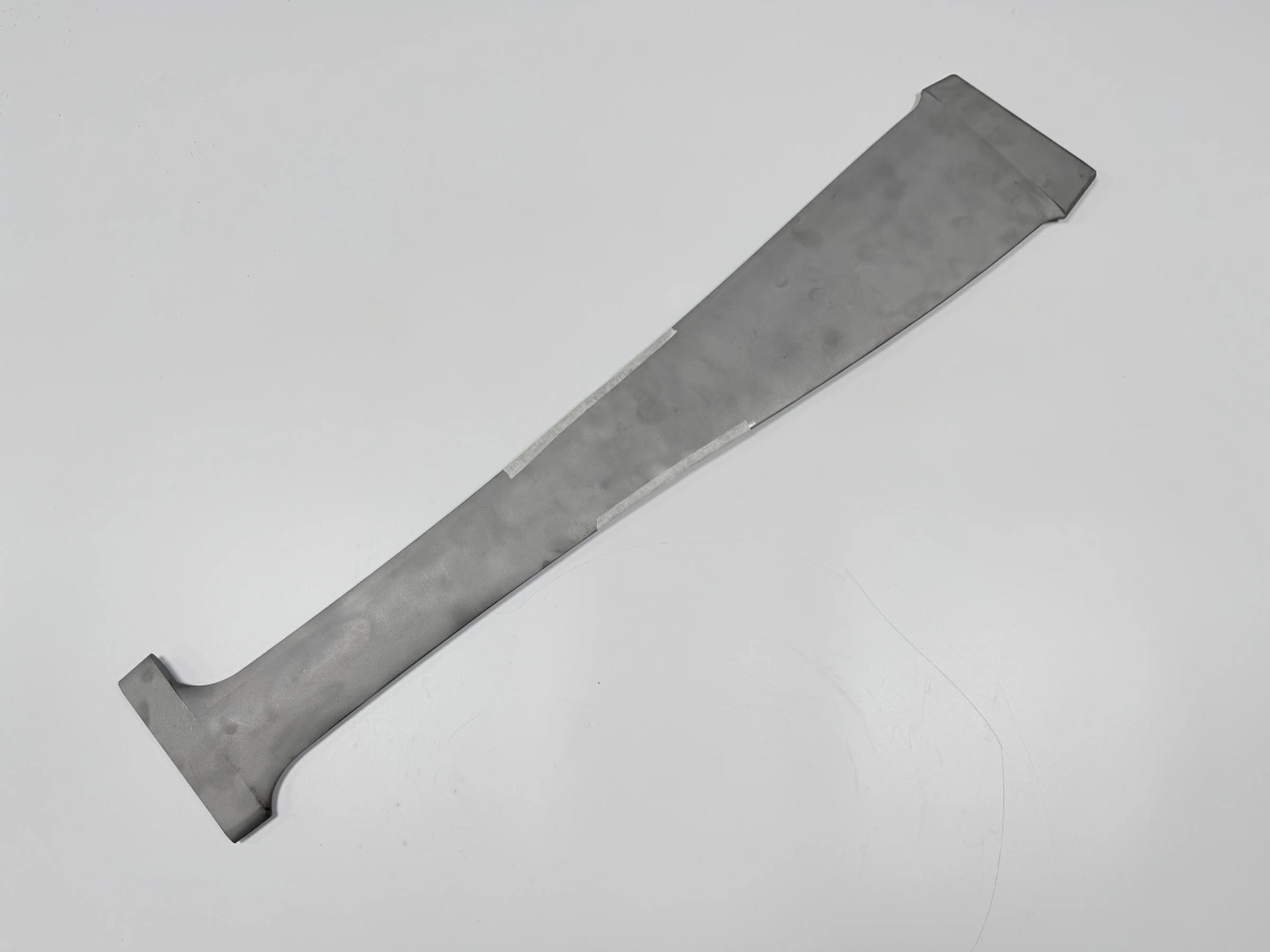
CNC post-machining is often the step that turns a printed metal blank into an assembly-ready part. Metal additive manufacturing can create near-net geometry, internal passages, and lightweight structures, but threads, bores, datum pads, sealing faces, bearing seats, and precision mounting features usually need a subtractive finishing plan.
The quote changes when machining is defined early. If a buyer sends only a STEP file, Neway can review printability, but it may not know which faces control assembly or which tolerances belong to the finished part. A drawing that separates as-printed surfaces from CNC-finished features prevents the quote from becoming a guess.
Neway reviews print-plus-CNC projects by checking material, build orientation, support contact, heat treatment sequence, machining stock, datum access, EDM needs, and final inspection records. The goal is not to machine every surface. It is to finish the surfaces that control function, sealing, location, wear, and assembly.
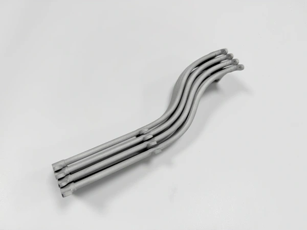
Printed Metal Blanks Still Need Functional Interfaces
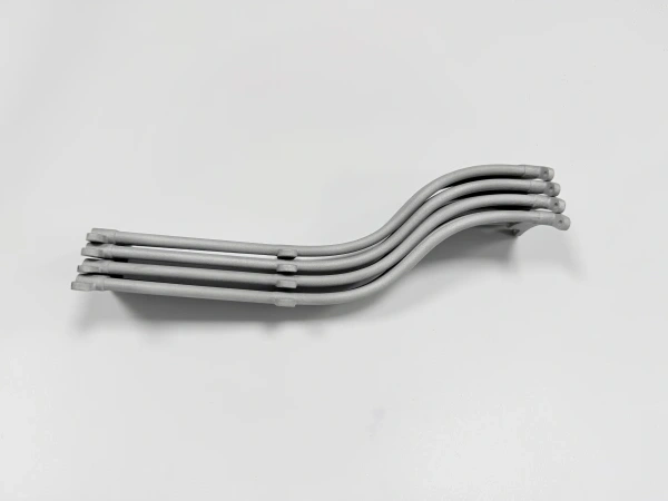
Powder bed fusion and other metal AM routes are useful when geometry is hard to machine from solid stock. That does not mean the printed surface is the correct acceptance surface for every feature. A printed bracket may still need flat mounting pads. A manifold may need machined ports and sealing grooves. A titanium part may need final bores and threads after stress relief.
CNC machining should be tied to function. If a surface only clears adjacent parts, it may remain printed or blasted. If a surface locates another component, seals fluid, carries a bearing, or controls a datum, it should be reviewed for machining. That distinction saves cost because the expensive work is applied to the surfaces that actually matter.
Buyers should also decide whether the first order is a fit-check prototype or a production-intent part. A prototype may use simplified machining on only a few interfaces. A repeat low-volume part may require stable datums, machining fixtures, and documented inspection on every critical feature.
The practical review is often a make-or-buy boundary inside the same part. Additive manufacturing may be responsible for the internal form and material-efficient blank, while CNC is responsible for the interfaces the assembly actually touches. The RFQ should make that split visible so purchasing can compare suppliers on finished-part scope instead of comparing a printed blank against a machined component.
Datum Strategy Should Be Chosen Before the Build
The datum plan should not wait until the printed blank arrives at the machining center. Build orientation, support removal, heat treatment, and HIP can all affect how the part is held and measured. If the drawing has no clear datums, the machinist may need to choose temporary references that do not match the final assembly condition.
Datum pads, fixture tabs, sacrificial bosses, or extra stock can be added to the printed blank so CNC has a stable reference. These features may look unnecessary in the finished CAD model, but they can make the difference between repeatable machining and a risky setup. If the buyer removes all temporary features from the model before quoting, the finished-part route may become more expensive.
For titanium 3D printing, datum planning is especially important when thin walls, residual stress, or oxygen-sensitive handling requirements are involved. For superalloy or stainless parts, support scars and thermal movement can also affect where a reliable machining reference should be placed.
Sequence matters as much as datum choice. If stress relief, heat treatment, or HIP is required, final machining is usually reviewed after those operations because the blank can move. Some parts may need rough machining first to create reference surfaces, then thermal processing, then finish machining. That sequence should be quoted intentionally rather than discovered after the first operation.
Feature to finish | Why CNC or EDM is reviewed | Planning detail before printing | Inspection evidence |
|---|---|---|---|
Threaded holes | Printed threads are not normally the final assembly feature. | Leave material for drilling, tapping, thread milling, or inserts. | Thread gauge, CMM location, or drawing-specific check. |
Bores and bearing seats | Roundness, diameter, and position often control function. | Orient and stock the blank so the bore can be reached. | CMM, bore gauge, or roundness report when required. |
Sealing faces | Surface condition and flatness can control leakage. | Protect the face from support scars and leave machining allowance. | Flatness, surface finish, and leak-related checks if specified. |
Datum pads | They control final machining and inspection alignment. | Add pads or tabs that survive heat treatment and support removal. | CMM report tied to the drawing datum scheme. |
Sharp slots or internal corners | Tool access may be limited with standard CNC cutters. | Review whether EDM is needed for narrow or hard-to-reach geometry. | Dimensional check, profile check, or surface report. |
Machining Allowance Is a Design Decision
Machining allowance should be placed where finishing is required, not added uniformly to the entire model. Too little stock risks leaving printed surface in a functional area. Too much stock increases build volume, support, machining time, and distortion risk. The correct allowance depends on material, geometry, thermal processing, fixture access, and final tolerance.
The buyer should mark which faces may remain as printed and which faces must be machined. If the drawing applies tight profile or surface finish requirements to all outer walls, the supplier may have to quote broad machining even where it adds no functional value. A clearer drawing can reduce cost by limiting CNC to the real interface surfaces.
Allowance also affects build orientation. A surface that needs machining should not be placed where support scars, powder traps, or tool access make finishing unnecessarily difficult. A small change in orientation or temporary stock placement can reduce the number of setups. For low-volume production, that decision may matter more than the raw printed volume.
Allowance location | Reason to add stock | Risk if not defined | Buyer note that helps |
|---|---|---|---|
Mounting pads | Final flatness and height control. | Printed surface may not meet assembly requirement. | Identify mating part and flatness requirement. |
Ports and bores | Tool path and final diameter control. | Hole may need rework or cannot be reached. | Mark critical diameter, depth, and orientation. |
Sealing lands | Leak prevention and surface finish control. | Support marks or roughness remain on sealing surface. | State sealing medium and finish requirement if known. |
Temporary tabs | Workholding after heat treatment or support removal. | Part may lack a stable machining reference. | Allow removal after final machining. |
When EDM Belongs in the Post-Machining Plan
EDM machining may be useful when a printed metal part has hard material, narrow slots, delicate features, internal corners, or surfaces that are difficult to reach with rotating tools. EDM is not a replacement for every CNC operation. It should be used where tool access, material hardness, geometry, or surface requirement makes it a better finishing method.
EDM can change quote scope because it adds setup, electrode or wire path planning, surface considerations, and inspection needs. If EDM is required for a slot, internal feature, or surface finish, it should appear in the RFQ rather than being discovered after printing. The buyer should mark which features need EDM and which features can be finished by conventional milling, drilling, tapping, or reaming.
Inspection Should Follow the Machining Sequence
CMM inspection usually belongs after final machining because it verifies the finished datum scheme, bore positions, mounting pad relationships, and critical interfaces. In-process checks may still be needed after printing or heat treatment when the blank could move before CNC. CT, visual review, surface checks, or thread gauges may be added when the drawing requires them.
Inspection should match risk. A prototype bracket may need only key dimensions. A sealed manifold may need port geometry and sealing-face checks. A medical or aerospace-related component may require buyer-defined records and acceptance criteria. Neway can support manufacturing and inspection planning, but qualification requirements should come from the buyer's drawing and specification.
When several suppliers are compared, ask whether the price includes machining fixtures, tool access review, post-machining deburring, thread verification, and dimensional reporting. These items can be small in a prototype quote but significant in a repeat order. A quote that only says "CNC included" may still leave uncertainty about which surfaces are finished and which records will be delivered.
Quote Data for a Print-Plus-CNC Project
For a reliable quote, send the STEP file, 2D drawing, material grade, quantity, application environment, printed-process preference if fixed, heat treatment or HIP requirements, critical dimensions, datum scheme, machined surfaces, threads, bores, sealing faces, surface finish, EDM needs, inspection records, and target delivery window. Identify whether the part is a prototype, engineering sample, or repeat low-volume order.
If cost control is important, ask Neway to separate printed blank scope, CNC post-machining, EDM if needed, surface treatment, and inspection records. That makes it easier to decide which features must be finished now and which can remain as printed during early prototype review.
Related FAQs