
Can HIP improve the wear resistance of 3D printed components?
Can HIP improve the wear resistance of 3D printed components?
HIP does not directly polish a wear surface or supply a universal wear-resistance increase. It can support wear performance when suitable closed internal porosity, inconsistent bulk condition, or a later material-state requirement is contributing to damage. Wear is usually controlled by the surface roughness, hardness, microstructure, counterface, normal load, motion, lubricant, temperature, and debris. Select HIP only when its densification or thermal mechanism is connected to the wear failure, then verify the finished surface and the actual contact condition.
Bulk and Surface Mechanisms
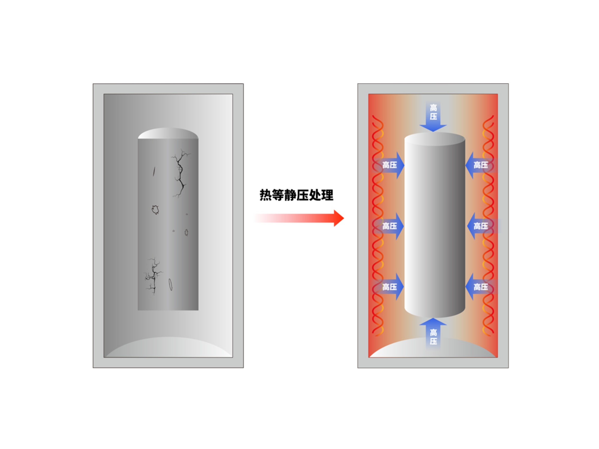
A closed pore below a loaded surface can reduce local support and become a crack or pit origin. HIP may reduce that pore under a qualified cycle because pressure and heat promote creep and diffusion. The response depends on pore closure, material grade, atmosphere, hold, cooling, and final heat treatment. A surface-connected crack, adhered particle, machining notch, or rough edge is not automatically corrected. The wear track can still fail if the counterface or lubricant is wrong even when internal indications improve.
Hardness and wear are not interchangeable. A harder condition can reduce a particular wear scar under a stated load, but it can also reduce toughness or make an edge chip. Inconel 718, Inconel 625, Ti-6Al-4V, 17-4 PH, and H13 use different strengthening and thermal routes. Keep the later heat treatment visible, and measure the surface after surface treatment or machining. A polished coupon cannot establish the behavior of an as-built production interface.
A wear buyer should first identify whether the damage is adhesive wear, abrasive wear, erosion, pitting, or fatigue of the near-surface material. A closed pore under a contact can provide a weak site for a pit, while rough peaks can raise friction and remove counterface material. HIP may address the first mechanism under a qualified cycle, but it does not remove the second. Select HIP for a wear component only when the internal defect is shown to participate in the damage, and keep the final machining or coating route visible.
For a conformal-cooling mold insert, select HIP when a mapped internal indication threatens channel leakage or cyclic cavity loading; verify channel pressure, cavity dimensions, hardness, roughness, and wear after polishing. For a 17-4 PH actuator pin, choose the final condition from load, fit, lubrication, and corrosion exposure; verify diameter, roundness, hardness, wear scar, and corrosion. For a titanium sliding bracket, choose HIP only when porosity is linked to the failure and verify the bearing surface separately. These are different decisions even though all three involve wear.
Design a Matched Wear Test
Use a representative method such as ASTM G99, ASTM G65, or ASTM G133 only when the contact mode fits the method. State normal load, speed, motion, distance, counterface, lubricant, temperature, atmosphere, roughness, hardness, sample orientation, conditioning, wear volume or mass calculation, and acceptance rule. Compare HIP-treated and reference parts with the same material lot, build orientation, machining, edge radius, and final surface. If one group is aged, polished, or coated after HIP, report the combined route.
Measure the wear track and inspect debris, pits, delamination, or fracture. Map hardness at the loaded region and record dimensional change or scar depth. If the treatment changes porosity but the fracture or wear origin is a rough surface, the expected benefit may not appear. If a surface coating carries the wear load, qualify adhesion, thickness, thermal cycling, and the interface separately. A wear result has meaning only under its stated contact and final condition.
Application Decisions
For an H13 conformal-cooling mold insert, select HIP when internal defects threaten cavity fatigue or channel leakage and the cavity has enough stock for movement. Verify channel leakage, mapped hardness, cavity dimensions, roughness, corner condition, and wear under the relevant polymer contact. For a 17-4 PH actuator pin, choose a condition from load, lubrication, corrosion, and fit; verify diameter, roundness, hardness, roughness, wear volume, and corrosion exposure. For a titanium sliding bracket, select HIP only when internal porosity is linked to the failure; verify the bearing surface separately.
Wear evidence should report the failure mode observed, not only a lower mass loss. Inspect the track for pits, delamination, transfer film, cracking, or embedded debris, and relate those observations to the internal indication and final surface. If the treated specimen is polished or coated while the reference is as-built, the comparison measures a combined route. If the result is sensitive to temperature or lubricant, repeat the condition that represents service. A part should remain on hold when the test method does not reproduce the contact or when a surface-connected defect is unresolved.
RFQ and Limits
Provide alloy and lot, additive route, orientation, defect evidence, wear mode, load, motion, speed, counterface, lubricant, temperature, environment, service cycles, final heat-treatment condition, machining and coating sequence, roughness, dimensional tolerance, inspection, quantity, and acceptance authority. Request cycle records, hardness maps, dimensions, roughness, wear data, fracture or debris analysis, and NDT where relevant. HIP alone is not evidence of longer service life. Release the wear claim only in the measured final condition.
If this question concerns a failure mechanism, compare the HIP processing service after the suspected cause and test condition are identified.
For a controlled production decision, request the heat-treatment service when the final state and deviation path need traceable evidence.
.webp)
