What are the typical applications for high-precision EDM machining?
What are the typical applications for high-precision EDM machining?
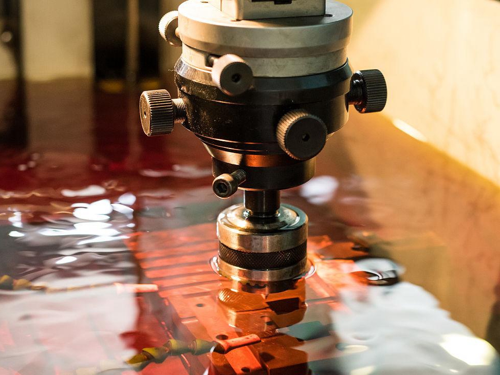
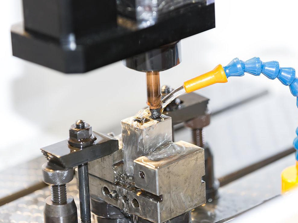
Typical applications for high-precision EDM include aerospace fuel and cooling features, medical-development instruments and implants, hardened tooling cavities, micro-slots, thin conductive contours, and complex inserts. The common reason is not that EDM automatically creates a smaller number; it is that controlled electrical discharge can remove conductive material with little continuous cutter force while reaching hard or intricate geometry. The application still needs a defined tolerance, datum, material state, access route, surface-integrity condition, and final inspection. A high-precision claim is credible only when the actual feature and service risk are connected to evidence.
Aerospace Applications
Aerospace inserts, fuel injectors, manifolds, turbine details, and cooling passages can combine hard nickel or titanium alloys, thin walls, narrow openings, and fatigue-sensitive surfaces. Wire EDM may be selected for an accessible through-profile or slot when cutter force and tool wear threaten the contour. Sinker EDM may be selected for a blind cavity reached by a shaped electrode. The choice depends on access, feature length, wall stiffness, and the ability to flush and clean the gap. Verify profile and position against the drawing, inspect recast or microcrack condition when fatigue matters, and perform flow or leak testing when the feature carries fluid.
For an aerospace fuel-nozzle insert, define build orientation, heat-treatment state, machining allowance, inspection temperature, and final cleaning before quoting a micron-level target. A bright or accurate opening cannot prove the bottom of a passage. Use borescope, dimensional, roughness, cleanliness, flow, or leak evidence appropriate to the feature. A coupon can screen a parameter family, but it cannot replace component verification when stiffness, porosity, or service loading differs.
Medical and Development Applications
Medical-development instruments, small cutting features, fluid-handling prototypes, and development implant components may need fine geometry, controlled edges, and cleanable surfaces. EDM can be useful for a conductive hard alloy or delicate contour, but a surface appearance or tight dimension does not establish biocompatibility, sterilization compatibility, clinical safety, or regulatory approval. Define the contact surface, alloy grade, printed and heat-treated states, cleaning chemistry, sterilization exposure, edge condition, roughness, residue limit, and responsible approval authority.
For a development instrument cavity, choose EDM only when the wire or electrode can reach the actual feature and the measurement method can inspect the bottom and sidewall. After unclamping, inspect dimensions again because a thin printed wall may spring back. Separate development screening from production qualification and keep the final report tied to the actual material lot and process route.
Tooling and Mold Applications
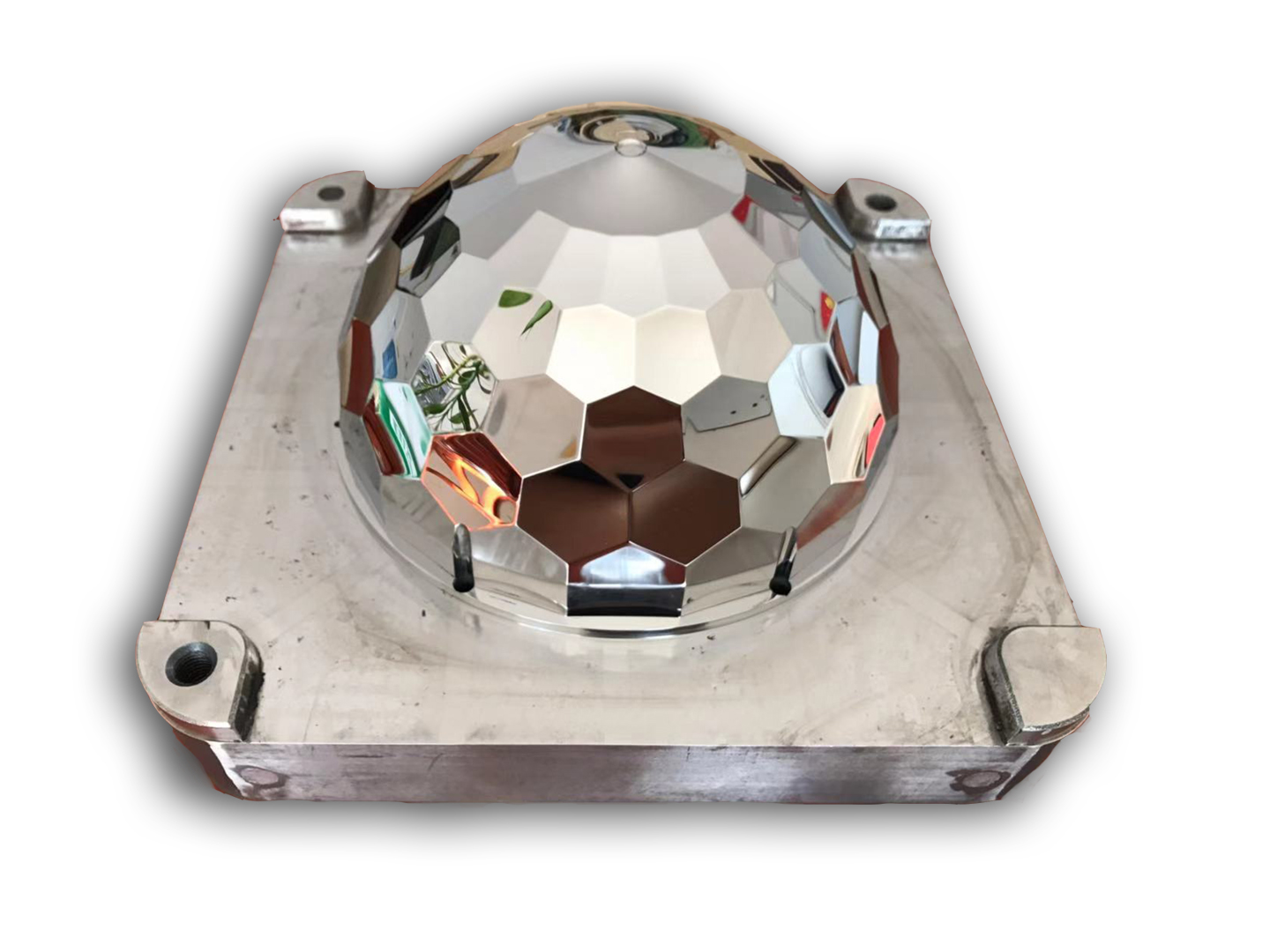
Hardened mold cavities, die inserts, punches, and conformal-cooling tooling can benefit from sinker EDM when a shaped electrode reaches a deep or complex feature. The electrode form, wear compensation, orbiting, flushing, and corner strategy affect the transferred geometry. A finishing pass may reduce crater size, but polishing can still be required for the final tool surface. Reserve an allowance, inspect the cavity floor and sidewalls separately, and remeasure after polishing or coating. The surface-treatment sequence must be part of the final tolerance chain.
Micro-Features and Inserts
Micro-slots, fine ribs, thin inserts, and small conductive apertures are often selected for EDM when a cutter cannot reach the feature without excessive force or tool deflection. The risk shifts to wire stability, gap debris, thermal loading, edge loss, and measurement access. Define minimum wall thickness, entry route, support plan, remaining stock, edge radius, and inspection locations. Do not infer a two-micron feature from machine resolution or from an open witness surface.
For a micro-slot in a printed aerospace bracket, choose wire EDM when the wire can enter and exit without weakening the support; verify slot width, taper, edge condition, and the unclamped profile. For a deep medical-development channel, choose sinker EDM only when the electrode and dielectric can reach the full depth; verify cleaning, residue, roughness, and dimensional results at the bottom as well as the opening. A linked EDM application review should state whether the tolerance is a trial target or a production limit. These examples show why the same advertised tolerance can carry different practical risk.
Application RFQ and Release
Provide CAD and drawing revision, datum scheme, feature tolerance, material grade and lot, build orientation, heat-treatment cycle, access restrictions, allowance, quantity, surface condition, recast or HAZ limit, functional load or fluid, cleaning, inspection method, and acceptance authority. Request the wire or electrode plan, parameter family, calibration record, workholding datum, dimensional report, roughness result, surface-integrity evidence, and nonconformance disposition.
For an aerospace cooling insert, choose wire EDM when the profile is accessible and low cutter force protects the wall; verify profile, recast, cleanliness, and flow. For a tooling cavity, choose sinker EDM when the electrode reaches the deep feature; verify corners, roughness, and final dimensions after polishing. For a medical-development component, select EDM only after contact, cleaning, sterilization, and approval boundaries are defined. High-precision EDM is an application decision with evidence, not a generic label for every small feature.
Before approving this application route, check the electrical discharge machining edm against the part's operating condition, critical feature, and acceptance limit.
For supplier comparison, use the CNC machining service to separate a process capability statement from evidence on the completed part.