How does EDM achieve a mirror finish on 3D printed parts?
How does EDM achieve a mirror finish on 3D printed parts?
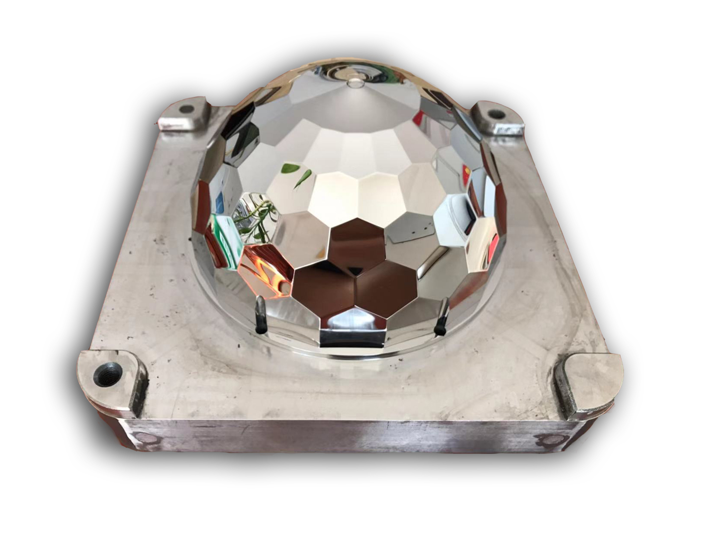
EDM can create a mirror-like finish on a conductive 3D-printed metal surface by using controlled electrical discharges to remove small volumes of material without direct cutter contact. The result comes from a qualified sequence of roughing and finishing passes, stable dielectric flushing, suitable wire or electrode access, and a final inspection method. The word “finishing” in a machine program does not establish the result. The printed alloy, thermal history, porosity, machining allowance, surface location, and required visual or roughness limit determine whether a reflective surface is practical. The EDM service route should be selected after the part and its acceptance condition are reviewed.
Discharge Mechanism
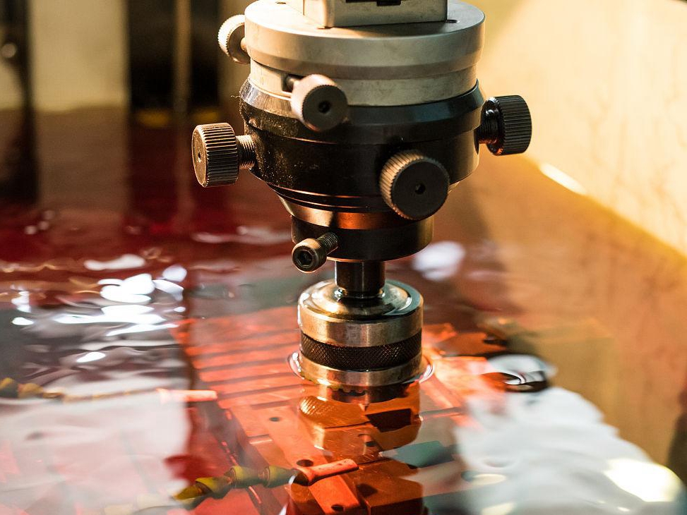
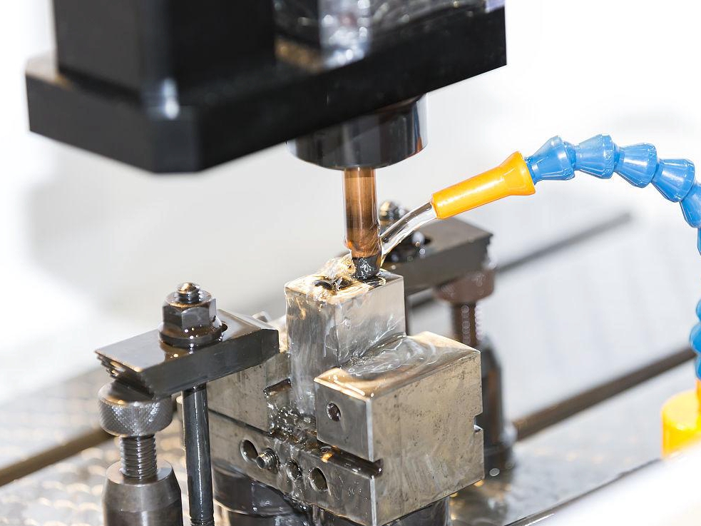
A controlled voltage creates a spark across the dielectric gap between the tool and conductive workpiece. The spark melts or vaporizes a small volume, and flushing removes debris from the gap. Many small discharges can produce a finer texture than a high-energy roughing pass because the individual craters are smaller and the finishing allowance is controlled. Current, pulse-on time, pulse-off time, voltage, polarity, duty cycle, wire speed, and pass count control how much energy reaches the surface. If debris remains in the gap, unstable arcing can create pits, uneven gloss, or localized damage rather than a uniform finish.
Wire EDM and sinker EDM create different access conditions. Wire EDM requires a through-profile or entry hole and is suited to trimming or cutting an accessible contour. Sinker EDM uses a shaped electrode for a blind cavity or local detail, so electrode wear, form accuracy, orbiting, and flushing influence the finished surface. A deep cavity can show a different finish at its bottom and sidewall because debris evacuation and thermal conditions are not identical.
Roughing, Finishing, and Recast
Roughing removes the main allowance. Finishing passes can reduce roughness when their energy, flushing, and allowance are controlled. The remaining allowance can protect datums and edges only when it is measured before finishing. The recast layer is resolidified material left on the surface; it may contain altered phases, tensile stress, pores, or microcracks. A bright appearance or acceptable Ra does not prove that the recast is acceptable for fatigue or sealing.
For a fatigue-sensitive aerospace insert, define whether recast is removed, sectioned, or accepted under a project criterion. For a sealing land, inspect the surface and perform a leak test with the actual fluid, pressure, temperature, and dwell. For a cosmetic housing, define reflectance, haze, viewing distance, and allowable marks. The surface function determines the evidence.
Finishing passes can reduce crater scale only when pulse energy, flushing, remaining stock, and the final measurement method are recorded. If those controls are not demonstrated on the same alloy and geometry, quote the result as a development target with a specified mirror-finish capability to be verified.
Material and Geometry Conditions
Stainless steel, titanium, nickel alloys, tool steels, and copper alloys can be candidates, but the exact grade and condition matter. Conductivity, hardness, thermal conductivity, build orientation, lack of fusion, gas porosity, heat treatment, and surface contamination can change the process window. An internal surface also needs a practical electrical return, dielectric path, cleaning route, and inspection method. A wire or electrode that cannot reach the intended area cannot create a validated mirror finish there.
Workholding is part of surface control. Establish the datum after the specified stress-relief or heat-treatment step, support flexible sections without forcing them, and measure after unclamping. Clamping distortion or spring-back can move the reflective face even when its texture is acceptable. If a surface-treatment step follows EDM, record the allowance and inspect again after that step.
Because a mirror finish is a final surface state rather than a machine mode, the buyer should compare the as-printed face, the rough-EDM face, and the finishing-pass face separately. For an aerospace manifold insert component, select wire EDM when the accessible contour makes cutting force the controlling risk; verify profile, recast, and flow or leak performance after cleaning. For a tooling cavity component, select sinker EDM when a shaped electrode reaches the deep feature; inspect electrode wear, corner geometry, roughness, and final dimensions. These records show whether the reflective result came from a stable process or from an isolated sample.
Because recast thickness and microcrack risk are governed by pulse energy, alloy response, and flushing, a visual reflection cannot be the only inspection result. Measure the surface after the finishing pass and after any downstream treatment that can remove stock or change chemistry. For a fatigue-sensitive aerospace component, select a process only when a representative section or approved nondestructive method can verify the recast condition; for a tooling component, verify the cavity map and corner condition after polishing.
Measurement and RFQ Information
Define the roughness metric, measurement direction, cutoff and evaluation length when applicable, sample locations, instrument resolution, and visual comparison method. Record roughness, waviness, gloss or haze when relevant, dimensional results, edge condition, recast or HAZ evidence, cleanliness, and functional test results. Ask for the electrode or wire plan, parameter family, dielectric condition, number of passes, workholding datum, and nonconformance disposition. A supplier should state whether the result is a demonstrated capability or a development trial.
For an aerospace component, include the alloy and lot, build orientation, final thermal state, fatigue or flow risk, and required inspection authority. For a medical-development component, include cleaning and sterilization exposure and do not infer clinical approval from surface appearance. For a tooling cavity, include polishing allowance, corner radius, coating plan, and the final dimensional map. For an aerospace manifold insert component, select wire EDM when the contour is accessible and cutter force is the main risk; verify profile, recast, and flow or leak performance after cleaning.
For a tooling cavity component, select sinker EDM when a shaped electrode can reach the deep feature; inspect electrode wear, corner geometry, roughness, and final dimensions. EDM creates a mirror-like surface only when the discharge process, material state, geometry, and final evidence are treated as one controlled route. A supplier should also state the starting surface, remaining allowance, target measurement direction, cleaning condition, and disposition if gloss is uneven or a microcrack is found.
For a primary route decision, use the electrical discharge machining edm after the material, geometry, and service condition for this question are defined.
For downstream verification, consult the surface-treatment service when the final process state and acceptance evidence for this question must be recorded.