Ti-6Al-4V Service CNC Datums and Inspection Planning for Buyers
A Ti-6Al-4V 3D printing service quote becomes hard to compare when datum surfaces, machined interfaces, and inspection stages are left vague. The printed blank is only one step. For a finished titanium part, the buyer also needs to know where machining stock is planned, which features become datums, and when the part is measured.
This matters because Ti-6Al-4V AM parts may move during support removal, stress relief, heat treatment, HIP, and final CNC machining. If the drawing calls out threads, bores, sealing faces, flat mounting pads, or position tolerances, those requirements should not be assumed as as-printed features. They should be separated into printed geometry, machined geometry, and inspected geometry.
Neway reviews titanium RFQs by connecting the STEP file to the 2D drawing. We look for functional surfaces first: what locates the assembly, what seals, what carries a bearing, what controls bolt position, and what must be recorded for receiving. That review changes the route for titanium 3D printing service projects more than a general material note.
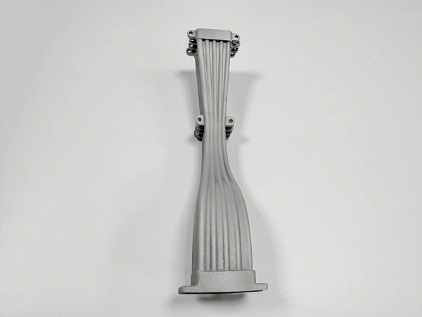
Datum Surfaces That Should Be Planned Before Printing
Datum planning starts before build orientation is chosen. A datum pad placed on a heavy support face may be machinable, but it may require added stock and a support removal route that protects the future reference surface. A datum on a thin wall can be risky because the wall may relax after cutting away supports. If the part must be inspected from A, B, and C datums, those surfaces should be manufacturable, reachable, and stable.
Ti-6Al-4V parts with broad mounting feet, bolted flanges, and bracket ears often need a small number of machined locating surfaces. The RFQ should identify which faces are only clearance surfaces and which faces define assembly position. Treating every surface as critical raises cost. Treating no surface as critical can create a part that prints well but cannot be installed or measured cleanly.
For precision metal additive manufacturing, the datum plan also controls fixturing. If Neway needs to rough machine temporary pads, clamp on sacrificial tabs, or preserve stock for final machining, those choices should be visible in the quote. Buyers should avoid approving a print-only offer when the drawing actually requires a finished datum structure.
Threads and Bores That Should Move to CNC
Threads, precision bores, bearing seats, dowel holes, and sealing counterbores are common places where Ti-6Al-4V service scope changes from printing to CNC machining. A printed pilot hole may help define material location, but it should not be confused with a finished threaded or close-fit feature. The drawing should show which holes are printed for relief and which are machined after thermal processing.
Thread orientation matters. A threaded hole near a support-heavy zone can collect surface damage or trapped powder before machining. Blind holes need enough access for drilling, tapping, inspection, and cleaning. Cross holes and intersecting bores should be reviewed for tool path access before the PO is released. If a bore is internal and cannot be reached by CNC, the acceptance method may need to change, or the design may need a split, plug, or alternate route.
Sealing faces deserve a separate note. Even if the surrounding titanium geometry is suitable for AM, a gasket face, O-ring groove, or fluid port seat usually needs a machined finish and a planned inspection method. The quote should distinguish cosmetic blending from functional machining because they are different operations.
Feature | Printed allowance concern | Machining stage | Inspection record | Buyer note |
|---|---|---|---|---|
Datum mounting pad | Needs stock after support removal and stress relief | Rough if needed, finish after thermal processing | CMM datum setup and flatness result when specified | Mark datum letters on the 2D drawing |
Threaded hole | Printed hole may only guide location and powder escape | Drill and tap after final datum is established | Thread gauge or dimensional confirmation as requested | Confirm blind or through hole access |
Precision bore | Orientation and heat movement can affect stock symmetry | Bore or ream after final clamping strategy is fixed | CMM or bore report tied to functional datums | State fit class or drawing tolerance |
Sealing face | Support contact should not be left on the final seal area | Finish machine after stress relief or heat treatment | Surface and profile evidence if required | Separate cosmetic finish from sealing requirement |
Thin bracket ear | May distort when supports are removed | Machine bolt face after stable clamping is available | Position check from the defined datum scheme | Allow DFM discussion before freezing orientation |
Why Heat Treatment Can Change Final Inspection Timing
Heat treatment is not just a material-process note. It can change when the part should be machined and when it should be inspected. Stress relief is usually discussed when residual stress may affect support removal, thin walls, or later CNC work. If the final tolerance applies to a machined surface, measuring before thermal processing may not prove the finished condition.
HIP should be separated from heat treatment in the quote. Hot isostatic pressing may be considered when internal soundness or fatigue-sensitive use is part of the acceptance requirement, but it is not a substitute for machining a datum or verifying a bore. If HIP is required by the buyer's specification, final machining and final inspection should normally be reviewed after the HIP route is known.
Thin walls, tall ribs, and unsupported arms require extra caution. Removing supports before stress relief may release distortion; keeping too much support until later may block machining access. A useful RFQ will tell us whether the buyer accepts a simpler prototype route or expects a production-intent sequence that can be repeated.
CMM Strategy for Ti-6Al-4V Finished Features
A CMM report should match the feature it claims to verify. If the part has a machined bore located from machined datums, the report should be created after those features are finished. If an internal channel cannot be reached by CMM, the buyer should not request ordinary CMM evidence for that geometry. Alternate inspection may be needed, depending on the feature and acceptance requirement.
GD&T notes should be reviewed before quotation. Position, profile, flatness, perpendicularity, and coaxiality can be reasonable on finished interfaces, but they may be unrealistic or unnecessary on freeform as-printed surfaces. The RFQ should separate critical-to-function dimensions from general envelope dimensions. That separation helps Neway price the machining and inspection package without treating every printed surface as a controlled interface.
Inspection records can also change delivery planning. A simple dimensional check on two machined faces is not the same as a full CMM report tied to multiple datums and annotated balloon dimensions. If material records, heat treatment records, HIP certificates from the processor, or surface finish checks are required, they should be listed before PO release rather than requested after parts are complete.
RFQ Notes for Prototype Versus Repeat Titanium Lots
Prototype and repeat titanium lots should not use the same acceptance language by default. A prototype may be used to confirm fit, assembly envelope, mass reduction, or machining access. In that stage, it can be practical to quote optional lines: printed blank, stress relief, selected CNC interfaces, surface finish, and selected inspection. A repeat lot needs a fixed route, including which datums are preserved, which operations are mandatory, and which records ship with each order.
Some Ti-6Al-4V parts should remain with conventional machining. If the geometry is a simple plate, spacer, shaft, ring, or flange with no internal channel, no weight-reduction benefit, and no consolidation value, AM may add support removal and thermal processing without solving a manufacturing problem. Neway will usually raise that point during DFM instead of forcing a titanium AM route onto a simple machined component.
For a reliable Ti-6Al-4V 3D printing service quote, provide the STEP file, 2D drawing, material grade, quantity, prototype or repeat-lot status, application environment, datum scheme, GD&T notes, threads, bores, sealing faces, machined surfaces, heat treatment or HIP expectations, surface finish needs, inspection records, and target delivery timing. If a buyer specification controls any operation, include it with the RFQ. That gives the quote a clear boundary: printed titanium blank, semi-finished part, or finished and inspected component.
Related FAQs