Copper Busbar 3D Printing Service Contact Face Review for Buyers
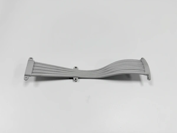
A copper busbar 3D printing service quote is controlled by contact faces before it is controlled by outer shape. A printed copper conductor may include bends, compact thermal paths, integrated mounting bosses, or geometry that would be difficult to machine from a simple bar. But the part still has to connect to terminals, bolts, insulators, cooling hardware, and measurement points. Those interfaces decide how much CNC machining, surface finishing, and inspection belong in the quote.
Neway reviews copper busbar and conductive insert RFQs by identifying the current path, the clamped contact zones, the bolt-hole strategy, and the surfaces that must not remain as printed. Copper 3D printing service can support compact electrical hardware, but the functional interface must be defined before the part is ordered.
This article is for buyers sourcing custom busbars, conductive inserts, power electronics parts, thermal-electrical connectors, and low-volume copper hardware. It focuses on quote boundaries: what should be printed, what should be machined, and what evidence may be needed to accept the finished part.
Contact Pads That Usually Need CNC Finishing
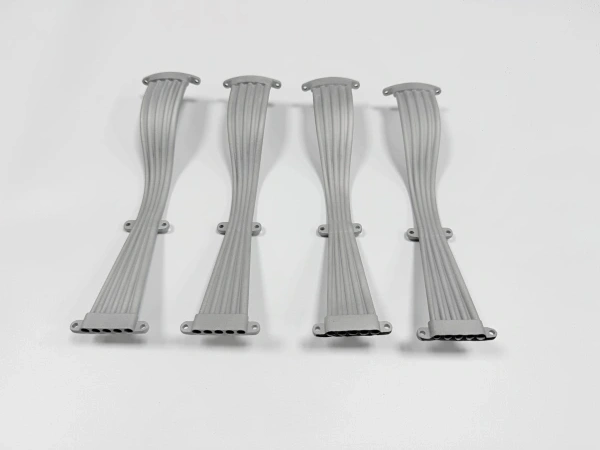
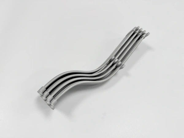
Contact pads should be reviewed as controlled surfaces. They may need flatness, clean metal exposure, bolt seating, plating allowance, or mating-surface alignment. A rough as-printed face can be acceptable on a non-contact wall, but it is rarely the right condition for a current-carrying pad unless the drawing allows it. If the pad carries significant clamp load or electrical current, it should usually be separated from general printed geometry.
CNC machining can define the pad after printing and any required thermal step. The buyer should mark which faces are active contact zones and which faces are only clearance or appearance surfaces. If both sides of a busbar need parallel contact faces, the RFQ should identify the datum strategy and the inspection method. Otherwise, one supplier may quote a raw printed surface while another quotes a machined finished part.
Contact pads also influence orientation. A support mark on the contact side may require extra stock and machining. A support mark on a non-functional side may be acceptable. The drawing should make that distinction before the build route is selected.
Bolt Holes and Slots That Should Be Dimensioned Separately
Bolted copper interfaces are sensitive to hole condition and pad geometry. Holes, slots, counterbores, and threaded features should be called out separately from the printed shape. A clearance slot may be printed near-net and then machined. A threaded hole may need tapping after print. A counterbore may need a machined seat so the fastener load is distributed correctly.
Slot shape can also affect quote scope. Long slots may need CNC finishing to control width and end radius. Thin copper around a slot can distort during support removal or machining. If the slot is used for adjustment, the drawing should state which surface controls contact and which surface only provides clearance. This helps Neway choose a practical route rather than assuming every hole can remain as built.
Hardware stack-up matters as well. Buyers should provide mating part information when possible: washer type, terminal thickness, insulator position, bolt access, and assembly direction. Without that context, a copper printed part may meet its standalone drawing but still create assembly difficulty.
Clearance around insulation and neighboring conductors should be included in the review. A compact printed copper part can route around other components, but a busbar still needs safe assembly space, tool access, and protection from unwanted contact. If the AM geometry reduces clearance, the buyer should mark keep-out zones and surfaces that must stay free of burrs, coating buildup, or support scars. These details affect finishing and inspection even when the electrical path is correct.
When Printed Copper Is Used for Integrated Thermal Paths
Many printed busbar-like parts combine current flow with heat movement. A conductive insert may also act as a heat spreader, cooling contact, or compact thermal bridge. In those cases, the quote should identify both electrical contact faces and thermal interfaces. A pad that transfers heat to a cooling plate may need machining even if it does not carry current.
C101 copper may be requested for pure copper conductivity, while CuCrZr or another alloy may be reviewed when strength, wear, or temperature behavior is more important. The buyer should define whether conductivity, mechanical loading, or thermal stability is the main reason for the material request. Neway will not assume that a copper alloy and pure copper can be swapped without engineering review.
Integrated thermal paths can make AM worthwhile when they reduce part count or create compact geometry. If the busbar is simply a flat strip, conventional machining or forming may be a better route. AM should be used because the geometry and function justify the extra build and finishing steps.
For combined thermal and electrical parts, the quote may need two acceptance paths. The contact pad may need dimensional and surface review, while the thermal path may need interface flatness, channel cleanliness, or assembly fit. If the buyer only specifies material grade, the supplier may not know which function controls the part. A short note on current direction, heat flow, and mating hardware can prevent a printed shape from being mistaken for a finished conductive assembly.
Interface | Print concern | Machining need | Surface note | Buyer drawing detail |
|---|---|---|---|---|
Bolted contact pad | Support texture or local unevenness can affect contact | Machine pad if clamp and current path are controlled | Keep clean metal or define plating route | Mark active contact zone and bolt pattern |
Long adjustment slot | Printed edge may not control sliding clearance | Finish slot width and end geometry when required | Protect edges from unwanted rounding | State clearance and adjustment function |
Thermal contact face | Rough surface can reduce contact consistency | Machine or finish to drawing requirement | Separate thermal face from appearance finish | Identify mating cooling surface |
Threaded connection | As-printed thread is usually not the final condition | Tap after print or review insert strategy | Deburr without contaminating contact area | Specify fastener and engagement need |
Sensor or measurement point | Small features may be damaged by support cleanup | Machine or protect if measurement depends on location | Keep measurement point accessible | Show probe or connector interface |
Surface Finish Notes That Affect Electrical Interfaces
Surface finishing for a copper busbar should be tied to function. Blasting may make non-contact surfaces uniform, but it may not be the right final condition for a contact pad. Polishing may improve an exposed interface but could round an edge that controls assembly. Plating or coating may be required by the buyer, but masked regions and final contact condition should be defined before quotation.
Surface treatment should not hide machining requirements. If a face needs machining, the quote should state whether finishing occurs before or after that machining. If the buyer needs a plated contact, the drawing should specify which surfaces receive plating and whether dimensions are measured before or after finishing. When this is unclear, price comparisons become unreliable.
Inspection should follow the same logic. A contact face may need dimensional inspection, a visual boundary check, or buyer-side electrical testing. Neway can provide manufacturing records when specified, but the buyer should define electrical acceptance requirements and test methods if they control receiving approval.
What to Confirm Before Ordering Printed Copper Busbars
Before ordering 3D printed copper busbars, provide the STEP file, 2D drawing, copper grade request, quantity, current path, thermal path, active contact faces, bolt holes, slots, threads, mating hardware, machined surfaces, surface finish notes, plating or coating expectations, inspection records, and prototype or repeat-lot stage. If electrical testing is required, state whether it is supplier-side or buyer-side.
The quote should separate the printed copper body from the finished interface package. That separation helps purchasing compare suppliers, helps engineering review manufacturability, and helps receiving understand what evidence belongs with the part. The goal is not only to print copper; it is to deliver a conductive component with contact geometry that matches the assembly safely.
Related FAQs
.webp)
.webp)