CNC Machining and Surface Finishing for AlSi10Mg 3D Printed Aluminum Parts
CNC Machining and Surface Finishing for AlSi10Mg 3D Printed Aluminum Parts
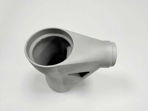
AlSi10Mg 3D printed aluminum parts can form complex lightweight structures, internal channels, thin-wall housings, and integrated features, but the as-printed part is not always ready for final assembly. Critical surfaces, precision holes, threaded holes, sealing faces, bearing seats, and flat mating areas usually require CNC post-machining or controlled surface finishing to meet functional requirements.
At Neway3DP, we provide AlSi10Mg printed aluminum parts with complete post-processing support. Our workflow can include powder bed fusion printing, support removal, heat treatment, CNC machining, surface treatment, dimensional inspection, and final delivery for custom finished aluminum 3D printed parts.
For buyers, the key question is not only whether AlSi10Mg can be printed. The more important question is whether the printed part can be finished to meet assembly accuracy, threaded connection, surface quality, sealing, and inspection requirements. With proper design planning and post-processing, AlSi10Mg 3D printed parts can be delivered as functional components rather than only rough printed blanks.
Why Post-Processing Matters for AlSi10Mg Printed Parts
Post-processing matters because powder bed fusion produces near-net-shape aluminum parts, not fully machined precision parts. The printed geometry can be highly complex, but as-printed surfaces may have layer texture, support marks, roughness variation, and dimensional deviation on critical features.
For functional aluminum parts, post-processing helps bridge the gap between additive manufacturing freedom and final assembly requirements. CNC machining is used where accuracy is needed. Heat treatment can improve stability. Surface finishing can improve appearance, corrosion resistance, cleanability, or functional surface behavior.
As-Printed Issue | Why It Matters | Common Post-Processing Route |
|---|---|---|
Support marks | Supported areas may be rough or unsuitable for visible or functional surfaces | Support removal, grinding, blasting, polishing, CNC machining |
Surface roughness | As-printed surfaces may not meet cosmetic, sealing, flow, or contact requirements | Blasting, polishing, surface treatment, localized machining |
Dimensional variation | Printed holes, datums, and mating features may not meet tight tolerance requirements | CNC machining, CMM inspection, dimensional report |
Residual stress | May affect dimensional stability during machining or service | Heat treatment or stress relief when required |
Unfinished threads | As-printed threads are usually not ideal for reliable assembly | Tapping, thread milling, threaded inserts |
As-Printed vs Machined AlSi10Mg Parts
As-printed AlSi10Mg parts are suitable for complex shapes, lightweight structures, prototypes, and non-critical surfaces. However, machined AlSi10Mg surfaces are usually required where the part must align with other components, hold bearings, seal fluids, accept fasteners, or meet tight dimensional tolerances.
The best manufacturing plan often combines both conditions. Non-critical areas can remain as-printed or blasted to control cost, while critical areas are CNC machined for accuracy. This approach keeps the design freedom of the powder bed fusion process while improving functional performance where it matters most.
Feature Area | As-Printed Condition | Machined Condition |
|---|---|---|
External non-critical surfaces | May be acceptable after support removal or blasting | Used if cosmetic or roughness requirements are stricter |
Assembly faces | May not provide enough flatness or positional control | Improves flatness, parallelism, and mating accuracy |
Holes | May need compensation for diameter and roundness | Drilled, reamed, bored, or CNC finished for accuracy |
Threads | Usually not recommended as final printed threads | Tapped, thread milled, or fitted with inserts |
Sealing surfaces | Usually too rough or uneven for reliable sealing | CNC machined or finished to defined roughness and flatness |
CNC Machining for Critical Features
CNC machining is used after AlSi10Mg printing when the part requires precision features. These usually include assembly faces, locating holes, threaded holes, sealing grooves, bearing seats, datum surfaces, and any areas where flatness, parallelism, perpendicularity, roundness, or surface finish must be controlled.
For aluminum 3D printed parts machining, the machining allowance should be planned before printing. If the model is printed exactly to final size without allowance, there may not be enough stock to finish critical surfaces. A 2D drawing is also important because it tells the supplier which dimensions are functional and which surfaces can remain as-printed.
CNC-Machined Feature | Why CNC Machining Is Needed | Design / RFQ Note |
|---|---|---|
Assembly face | Improves flatness, contact quality, and assembly fit | Define datum surface and required flatness on the drawing |
Locating hole | Improves diameter, roundness, and positional accuracy | Print undersized and finish by drilling, reaming, or boring |
Threaded hole | Improves thread strength and repeatable fastening | Use tapping, thread milling, or threaded inserts after printing |
Sealing groove | Controls groove geometry and surface finish for sealing performance | Provide groove dimensions, tolerance, and roughness requirements |
Bearing seat | Requires controlled roundness, diameter, and surface finish | Specify fit tolerance and inspection requirement |
Heat Treatment Options for AlSi10Mg Printed Parts
Heat treatment may be used for AlSi10Mg printed parts when the project requires improved stability, reduced residual stress, or application-specific mechanical performance. The need for heat treatment depends on part geometry, function, loading condition, and final assembly requirements.
For complex aluminum parts, heat treatment can help reduce deformation risk before or after CNC machining. It should be planned together with machining allowance and inspection requirements, especially for thin-wall structures, large housings, functional brackets, and precision aluminum assemblies.
Heat Treatment Purpose | Benefit for AlSi10Mg Parts | Typical Application |
|---|---|---|
Stress relief | Helps reduce residual stress from the printing process | Thin-wall housings, brackets, structural prototypes |
Dimensional stability | Reduces movement during CNC post-machining or assembly | Parts with machined datums, holes, and mating surfaces |
Mechanical property adjustment | Supports application-specific strength and performance requirements | Functional prototypes and small-batch aluminum parts |
Process reliability | Improves confidence before finishing and final inspection | Assembly-ready aluminum components |
Surface Finishing Options for 3D Printed Aluminum Parts
AlSi10Mg surface finishing may include support removal, blasting, polishing, localized sanding, chemical treatment, coating, or other surface treatment depending on the application. The goal may be visual improvement, roughness reduction, corrosion protection, cleanability, or functional surface control.
Customers often ask whether AlSi10Mg printed parts can be sandblasted, polished, anodized, or otherwise finished. The answer depends on the part geometry, surface condition, alloy behavior, coating requirement, and cosmetic expectation. Surface treatment should be confirmed before quotation because it may affect cost, lead time, masking, and inspection.
Surface Finishing Option | Purpose | Typical Use Case |
|---|---|---|
Support removal | Removes printed support structures and contact areas | All supported AlSi10Mg printed parts |
Sand blasting | Creates a more uniform matte appearance and reduces visible layer texture | Housings, brackets, covers, prototypes |
Polishing | Improves smoothness and appearance on selected surfaces | Visible parts, contact surfaces, flow-related areas |
Anodizing or coating | May improve appearance or corrosion resistance depending on requirement | Consumer-facing or industrial aluminum components, subject to feasibility review |
Localized finishing | Improves selected functional areas without over-processing the entire part | Sealing zones, mounting areas, visible surfaces |
Dimensional Inspection for Finished AlSi10Mg Parts
Dimensional inspection confirms whether finished AlSi10Mg parts meet the drawing requirements after printing, heat treatment, CNC machining, and surface finishing. Inspection planning is important because the features that matter for assembly are not always the same as the features that are easiest to print.
Common inspection methods include basic dimensional checks, 3D scanning, first article inspection, CMM inspection, surface roughness measurement, and final visual inspection. For precision aluminum assemblies, the inspection plan should focus on machined datums, holes, threads, mating faces, sealing grooves, and any customer-defined critical dimensions.
Inspection Method | Purpose | Typical Use Case |
|---|---|---|
Basic dimensional check | Confirms main dimensions and general drawing requirements | Prototype parts and non-critical components |
3D scanning | Compares complex freeform geometry against CAD data | Complex housings, organic shapes, lightweight structures |
FAI | Documents first article dimensions before batch production | Pilot batches and production-intent parts |
CMM inspection | Checks datums, precision holes, positional relationships, and critical features | Machined assembly parts and tight-tolerance features |
Surface roughness report | Confirms surface quality on sealing, contact, or visible areas | Sealing faces, bearing areas, flow surfaces, cosmetic surfaces |
Design Tips Before Quotation
Before requesting a quote, customers should define which areas must be printed as-designed, which areas can remain as-printed, and which areas require machining or surface finishing. This helps avoid unnecessary cost and prevents misunderstanding between a printed prototype and a precision assembly component.
The most important design step is to mark critical dimensions on a 2D drawing. If all surfaces are treated as critical, cost and lead time may increase unnecessarily. If no critical areas are identified, the supplier may not know where machining allowance, inspection, or surface finishing is required.
Design Tip | Why It Helps | Recommended Action |
|---|---|---|
Reserve machining allowance | Ensures enough stock remains for CNC finishing | Identify datum surfaces, bores, threads, sealing faces, and mating areas |
Mark critical dimensions | Separates functional tolerances from non-critical printed geometry | Provide a 2D drawing with tolerance notes |
Define thread requirements | Improves assembly reliability and quotation accuracy | Specify thread size, depth, insert requirement, and location |
Clarify surface finish | Prevents over-finishing or under-finishing | Separate visible, functional, sealing, and as-printed areas |
Share application environment | Helps choose heat treatment, finishing, and inspection route | Explain load, temperature, vibration, corrosion, thermal, or assembly requirements |
One-Stop Manufacturing Workflow
A one-stop workflow helps customers reduce supplier coordination and improve final part consistency. Instead of sending printed blanks to separate vendors for heat treatment, CNC machining, surface finishing, and inspection, Neway3DP can support the full process from printing to delivery.
This workflow is useful for functional aluminum parts used in consumer electronics applications, thermal housings, precision fixtures, and energy and power applications where compact cooling structures, flow paths, or machined interfaces may be required.
Workflow Step | Purpose | Customer Benefit |
|---|---|---|
Engineering review | Evaluate printability, support strategy, machining allowance, and finishing needs | Reduces redesign risk before production |
Powder bed fusion printing | Build complex AlSi10Mg geometry layer by layer | Supports lightweight and integrated aluminum structures |
Heat treatment | Improve stability or meet application-specific requirements | Reduces risk before final machining or assembly |
CNC machining | Finish critical holes, threads, datums, and mating surfaces | Improves assembly accuracy and functional fit |
Surface treatment | Improve appearance, roughness, corrosion resistance, or functional surface quality | Delivers parts closer to final-use condition |
Inspection and delivery | Verify dimensions, surface requirements, and documentation before shipment | Supports assembly-ready custom finished aluminum 3D printed parts |
What Information Is Needed for an AlSi10Mg Post-Processing Quote?
To quote precision AlSi10Mg 3D printing with CNC machining accurately, the supplier needs the 3D model, 2D drawing, quantity, post-processing requirements, inspection requirements, and final application environment. The 3D file helps evaluate printability and support layout, while the 2D drawing defines critical dimensions and finishing requirements.
For faster quotation, please provide the following information:
3D CAD model, preferably STEP, X_T, IGS, or STL format
2D drawing with tolerances, datum requirements, threaded holes, sealing surfaces, surface finish, and inspection notes
Required material, such as AlSi10Mg or another aluminum alloy
Quantity for prototype, functional validation, small-batch production, or repeat order
Critical machining areas, including assembly faces, locating holes, threads, bearing seats, sealing grooves, and datum surfaces
Surface finishing requirements, such as support removal, blasting, polishing, anodizing feasibility review, coating, or corrosion protection
Heat treatment or stress-relief requirements if applicable
Inspection requirements, such as dimensional report, 3D scan report, FAI, CMM report, material certificate, or surface roughness report
Application environment, including load, temperature, vibration, corrosion exposure, thermal performance, or assembly conditions
Target delivery schedule and shipping destination
FAQ
Is AlSi10Mg a Good Material for Custom Aluminum 3D Printed Parts?
What Tolerances Can AlSi10Mg 3D Printed Parts Achieve After CNC Machining?
How Much Does AlSi10Mg 3D Printing Cost for Prototype and Small-Batch Parts?
Can AlSi10Mg 3D Printing Replace CNC Machined Aluminum Parts?
What Post-Processing Is Recommended for AlSi10Mg 3D Printed Parts
.webp)