
How Tight Must Burner Liner Flange Flatness Be?
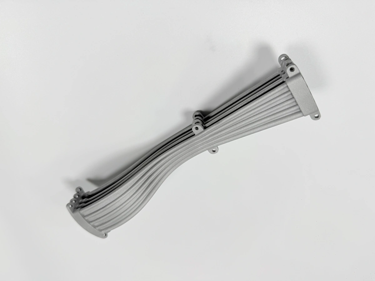
Burner liner flange flatness is held to 0.05 mm after the finish cut, and the three quartz windows share that plane. The 1.8 mm GH3536 wall carries the flange and the window lands as one shell, so a single machined face sets the assembly limit. Roughness on that face stays at Ra 1.6 µm or better, and the frames are cut in the same setup as the flange.
What flatness does a quartz window frame need?
A quartz window frame needs 0.05 mm coplanarity with the flange, because the quartz seat and the burner body clamp onto one shared face. The as-printed frame arrives rough and slightly warped, so the frame land is cut in the same setup as the flange and inherits the same datum. Three openings sit on the front wall of the 1.8 mm shell, and each one is a machined land rather than an as-built surface.
The liner is not a pressure boundary, so 0.05 mm does not buy a seal. That tolerance buys window alignment instead. A frame that sits 0.1 mm out of plane tilts the quartz in its seat, and the tilt shifts the optical axis across the measurement plane where the laser diagnostics and the high-speed camera work.
Window frame coplanarity is read across all three frames in one coordinate system, not frame by frame. Two frames can each be flat to 0.05 mm and still miss each other by 0.1 mm, which preloads a quartz disc that spans an opening. That check belongs to burner liner window machining and runs on the same setup as the flange.
How is burner liner flange flatness measured after machining?
Burner liner flange flatness is measured on a coordinate measuring machine (CMM) with the part free of clamps and fixtures. The CMM fits a least-squares plane to the machined face and reports peak-to-valley height against the 0.05 mm limit. Every liner is measured that way, not sampled from a batch, and the report names the face and the datum used.
Measuring burner liner flange flatness in the clamped state hides the release movement. A 1.8 mm wall stores elastic energy under 0.5 MPa of jaw pressure, and the face can move 0.02 mm to 0.05 mm when the jaws open. We measure after release, on the bench, at room temperature, and again after the hole pattern is cut.
Roughness is traced with a stylus against ISO 4287, and the flange and window lands both hold Ra 1.6 µm. The liner flange face tolerance follows the cut face, not the printed blank, and the unmachined shell keeps the general tolerances of ISO 2768-1. The faces are cut on a five-axis CNC machining center from the datum holes rather than from the printed skin.
When does a flatter face not fix the fit?
A flatter face does not fix the fit when the error sits in the datum or in the mating body. The two 8 mm datum holes place every machined feature, and a hole position that drifts past 0.02 mm pulls the flange off the bolt pattern while flatness still reads 0.05 mm. The datum chain behind those two numbers sits inside our 3D printed burner liner route notes.
A bowed body face is the other case. A liner flat to 0.02 mm will still rock on a body face that is out by 0.1 mm, and the gap shows up as a tilted window rather than a flatness failure on the report. A contact pattern on the assembly face catches that before the bolt pattern is blamed.
Two conditions fall outside this answer. A pressure boundary needs a machined seal groove and a pressure test, and this liner carries neither. A wall below 0.8 mm cannot be held against the cutter well enough for 0.05 mm to mean anything, so the callout moves to a different process and a different fixture.
Send the flange outline, the window layout and the mating body face. We will check the stock on each face, name the datum sequence, and quote the superalloy 3D printing blank that sits behind the machining step. One review covers both the printed blank and the finishing plan.
.webp)