
Titanium Aerospace Bracket AM Thin Wall and Support Risk Review
A titanium aerospace bracket can look ideal for AM because the shape is light, organic, and difficult to machine from billet. The quote still depends on details that are easy to miss: thin ribs, lug thickness, support contact, residual stress, bolt hole finishing, datum pads, and inspection evidence. A bracket that prints successfully may still fail the buyer's assembly or measurement requirement.
Neway reviews titanium bracket RFQs by separating the load-carrying printed body from the finished interfaces. The body may justify titanium 3D printing service, while fastener holes, mating pads, dowel locations, and flat datum surfaces often move to CNC. This distinction affects cost, lead time, and receiving inspection.
This article is for buyers evaluating titanium aerospace bracket 3D printing service for prototype or low-volume work. It does not assume an aerospace approval; the final route remains subject to the buyer's drawing, specification, qualification plan, and engineering review.
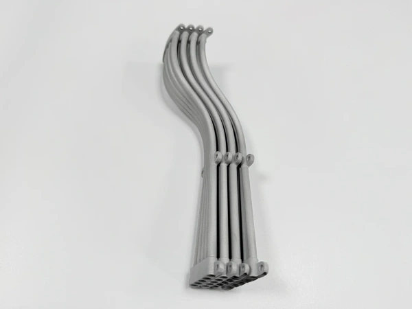
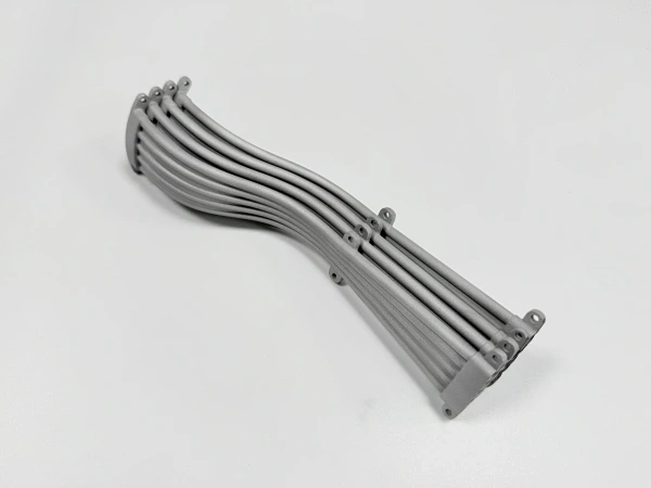
Thin Wall Areas That Change Titanium Bracket Orientation
Thin bracket walls and ribs should be reviewed before the build orientation is chosen. A rib that looks efficient in CAD may need support on one side, may distort when support is removed, or may place a critical face in a rougher surface direction. If the bracket has a thin web between two lugs, the orientation may be controlled by distortion risk rather than by the lowest support volume.
Buyers should mark which walls are functional and which are only weight-saving geometry. A cosmetic lightening pocket can tolerate a different surface state from a thin load path near a bolted joint. If every wall is treated as critical, the quote becomes heavier with machining and inspection. If no wall is marked, the supplier may choose an orientation that prints well but creates downstream risk.
For powder bed fusion, thin areas also affect powder removal and visual inspection. A closed pocket, narrow slot, or deep internal channel inside a bracket can trap powder or block cleaning access. That geometry should be reviewed before the buyer treats the bracket as a simple lightweight replacement.
Support Scars Near Lugs and Load Paths
Support contact is not only a cosmetic issue on an aerospace bracket. A support scar near a lug, fillet, or load path may require local machining, blending, polishing, or orientation change. If the drawing has fatigue-sensitive zones, no-support surfaces should be identified in the RFQ. A supplier cannot protect those areas if the drawing only says titanium bracket.
Large lugs and thick bosses can pull heat differently from thin webs. That mismatch may affect support strategy and residual stress behavior. A bracket with one heavy boss and several thin arms may need a route that balances thermal mass, support stiffness, and later removal access. The cheapest orientation may not be the one that protects the assembly faces.
Support removal should be checked against tool access. A support under a deep overhang can be difficult to remove without damaging nearby geometry. If the support is close to a later-machined pad, the risk may be manageable. If it is on an as-printed load path, the design may need a fillet change, drain opening, local stock, or different orientation.
Bracket feature | AM risk | Post-process need | Inspection concern | Design option |
|---|---|---|---|---|
Thin rib between lugs | Distortion after support release | Stress relief and careful support removal | Profile or position check if it controls fit | Add stiffness, change orientation, or relax nonfunctional surfaces |
Fastener lug | Support scars may sit near a loaded fillet | Local blending or machining away from the load path | Visual and dimensional check tied to drawing notes | Define no-support zones before quote |
Bolt hole pattern | Printed holes may not meet assembly position | Drilling, boring, or reaming after datums are made | CMM position from machined datums | Print pilot holes only if useful for machining |
Mounting pad | Flatness may shift through heat treatment | Finish machining after stable thermal route | Flatness and datum evidence when specified | Reserve machining stock on functional pads |
Deep lightening pocket | Powder and support access may be limited | Cleaning access review and possible local finishing | Visual access may be incomplete | Add access opening or redesign pocket geometry |
Bolt Holes That Should Be Machined After Printing
Bolt holes, dowel holes, threaded inserts, bearing seats, and counterbores should usually be planned as post-machined features when they control assembly. A printed hole can reduce material removal, but it should not be treated as the final aerospace bracket interface. The quote should state whether the hole is as-printed, drilled, tapped, bored, reamed, or inspected by CMM.
CNC machining access needs to be checked before printing. A tool must reach the hole without collision, the bracket must be held from stable surfaces, and the machining stock must remain after support removal and heat treatment. If a hole pattern wraps around a curved AM surface, datum pads may need to be added or preserved for workholding.
Threads in titanium need special attention because the printed surface condition and local support marks do not define a finished thread. If the thread is blind, cleaning and chip removal also matter. Buyers should state thread depth, insert preference, gauge requirement, and whether the threaded area is part of a critical assembly.
Datum Pads for Bracket CMM and Assembly Fit
Datum pads are the bridge between an organic AM bracket and a measurable assembly part. Without stable datum surfaces, a CMM report can become hard to interpret. The drawing should identify which face or pad becomes datum A, which edge or hole locates datum B, and what feature controls datum C. Neway can then plan machining and inspection in the same coordinate logic.
Heat treatment and support removal can change when inspection should happen. A bracket measured as a raw print does not prove a final machined bolt pattern. If the buyer needs final position evidence, the measurement should be after the relevant machining and finishing steps. If the bracket is only a prototype fit check, a reduced inspection package may be enough, but that should be stated.
For precision metal additive manufacturing, over-controlling nonfunctional freeform surfaces can raise cost without improving the assembly. The buyer should separate critical-to-function dimensions from reference envelope dimensions. This lets the quote focus machining and inspection where they actually protect fit. It also prevents avoidable CMM work on cosmetic bracket contours.
When the bracket moves from first article to a small repeat lot, the datum plan should be frozen. Changing a datum pad, support contact zone, or bolt-hole machining order after prototype approval can shift the inspection result even if the printed shape looks similar. Buyers should decide which prototype compromises are acceptable for repeat supply and which must be corrected before the next PO.
Design Changes That Can Reduce Support and Distortion
Small design changes can reduce support volume, removal risk, and distortion. A fillet added at a bracket root may reduce stress concentration and support demand. A drain or access opening can improve powder removal. A temporary machining tab can help workholding. A thicker local pad can preserve stock for final flatness without making the whole bracket heavier.
The buyer should also review whether the bracket is truly an AM candidate. AM is worth reviewing when the geometry uses curved load paths, internal cable or fluid passages, low-volume consolidation, or weight reduction that would be expensive by machining. Simple flat brackets, plates, spacers, and straight flanges may be better routed to CNC from titanium stock.
For a reliable RFQ, send the STEP file, 2D drawing, titanium grade such as Ti-6Al-4V or TA15 if specified, quantity, prototype or low-volume stage, aerospace specification notes, load path concerns, no-support zones, thin walls, lugs, bolt holes, datum pads, machined surfaces, heat treatment expectations, inspection records, and target delivery timing. Also state whether supplier DFM changes need buyer approval before printing. Neway can then quote the titanium bracket as a finished manufacturing route instead of a generic printed shape.
Related FAQs
.webp)
