Heat Treatment Post Process: Boosts Resistance to Wear And Fatigue for 3D Printed Parts
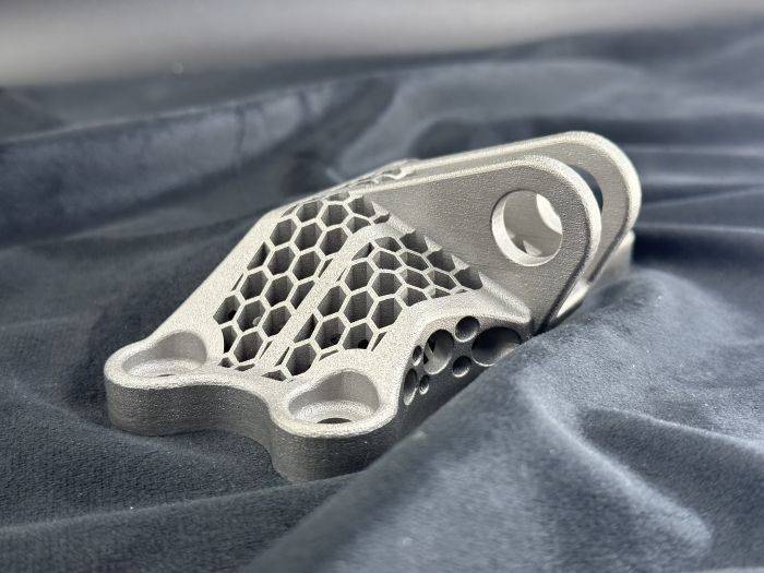
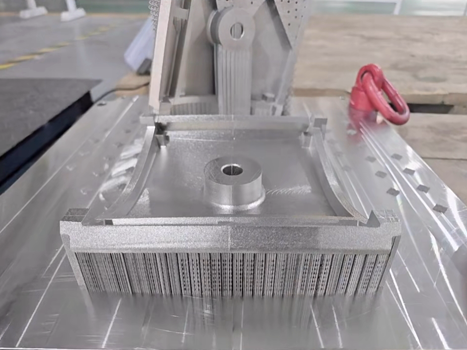
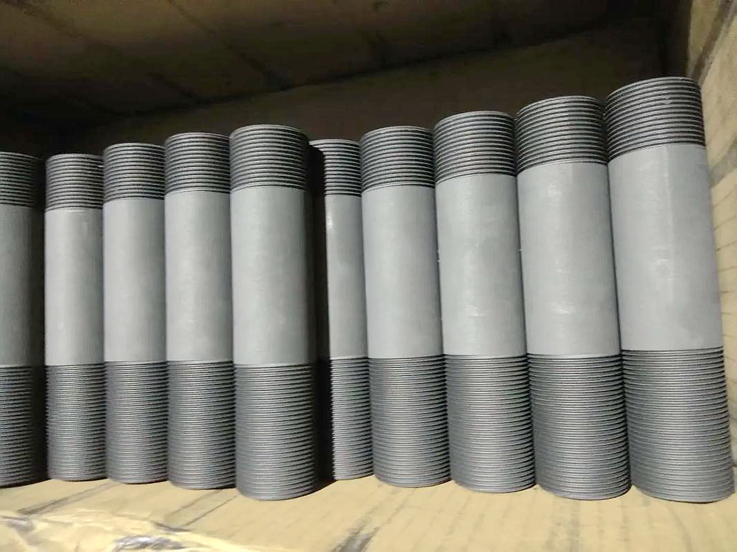
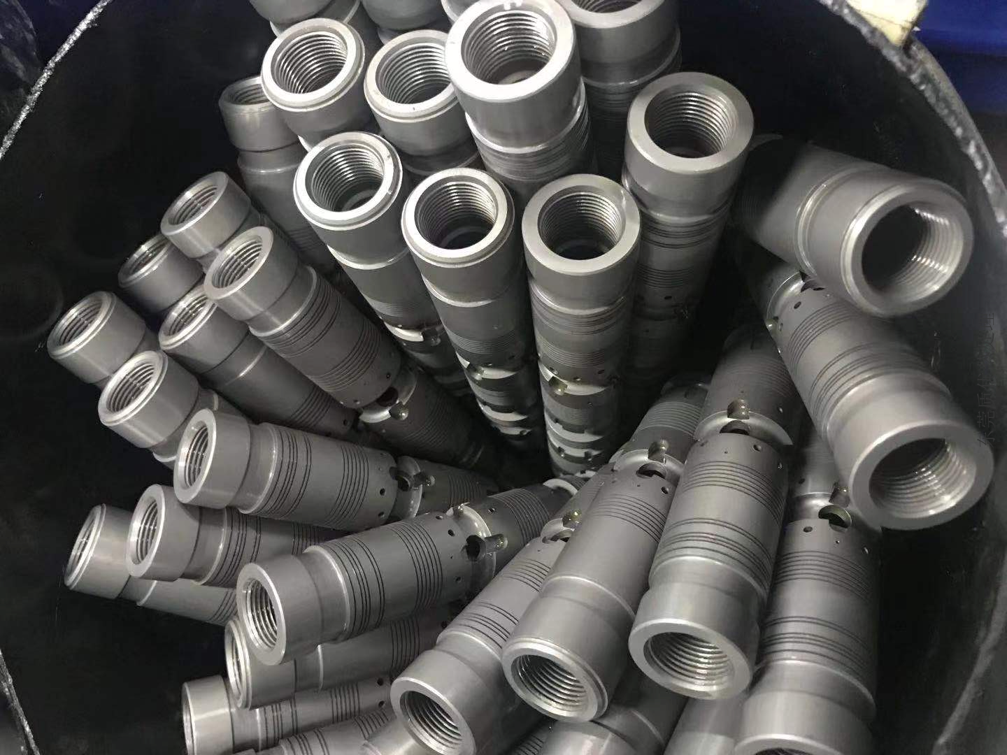 3D printing has emerged as a revolutionary method for producing complex and customized parts directly from digital designs. However, while 3D printed parts offer design flexibility and rapid production, they often suffer from material weaknesses, such as poor wear resistance and low fatigue strength. This is where heat treatment plays a critical role. Heat treatment processes can significantly improve the mechanical properties of 3D printed parts, including strength, hardness, and fatigue resistance. In this blog, we’ll explore how heat treatment enhances the mechanical properties of 3D printed parts and why it’s essential for high-performance applications.
What is Heat Treatment Post-Processing?
Heat treatment post-processing refers to controlled heating and cooling processes applied to 3D printed parts to modify their physical properties. These processes aim to enhance the material's performance by improving its strength, hardness, ductility, and fatigue resistance. Different heat treatment methods, such as annealing, quenching, and tempering, can be employed depending on the material used and the desired outcome.
For 3D printed parts, heat treatment helps resolve issues like residual stresses, poor material bonding, and surface roughness that can occur during the additive manufacturing process. These improvements are essential for parts used in aerospace, automotive, and medical devices, where performance and reliability are critical.
How Heat Treatment Boosts Wear and Fatigue Resistance
1. Reducing Internal Stresses
During the 3D printing process, parts can develop internal stresses due to uneven cooling rates and rapid solidification of material layers. These stresses can lead to part warping, cracks, and reduced mechanical strength. Heat treatment processes like stress-relief annealing are used to reduce these residual stresses. By heating the part to a specific temperature just below its melting point and then cooling it slowly, internal stresses are relieved, which minimizes the risk of distortion and improves the part's overall structural integrity.
2. Improving Surface Hardness
Heat treatment processes like quenching and tempering increase the surface hardness of 3D printed metal parts. During quenching, the part is heated to a high temperature and rapidly cooled, typically in water or oil. This process hardens the surface and improves wear resistance, essential for parts that undergo abrasive or frictional contact.
The part is reheated to a lower temperature after quenching in the tempering step. This reduces brittleness while maintaining hardness and improving toughness. The result is a part with high surface hardness for wear resistance but is also more resilient to cracking under stress, making it ideal for applications involving cyclic loading.
3. Enhancing Fatigue Resistance
3D printed parts, particularly those with complex geometries or internal features, can suffer from poor fatigue resistance, limiting their lifespan in certain applications. Heat treatment improves the fatigue resistance of 3D printed parts by refining the microstructure and ensuring better material consistency.
For example, heat treatment processes like solution annealing and aging can significantly enhance fatigue strength by promoting a more uniform and durable microstructure in titanium alloy parts used in aerospace or medical applications. This improvement is crucial for parts undergoing repeated stress cycles over their lifespan.
4. Improving Toughness and Impact Resistance
Parts subjected to impact or sudden force must have high toughness and the ability to absorb energy without fracturing. Heat treatment processes like tempering and annealing improve toughness by adjusting the material's microstructure. These processes reduce brittleness and improve the material’s ability to withstand impact without cracking, which is essential for parts exposed to dynamic forces in industries such as automotive and medical.
5. Enhancing Overall Durability
Heat treatment not only boosts resistance to wear and fatigue but also improves the overall durability of 3D printed parts. By refining the material properties, heat treatment ensures that parts can withstand harsh operating environments, such as high temperatures, aggressive chemicals, or abrasive conditions, without compromising performance or failing prematurely.
Heat Treatment Process | Effect on Mechanical Properties | Common Applications |
|---|---|---|
Stress-Relief Annealing | Reduces internal stresses and improves dimensional stability | Aerospace, automotive, medical devices |
Quenching | Increases surface hardness and wear resistance | Engine components, gears, aerospace |
Tempering | Balances hardness and ductility, improves toughness | Automotive parts, medical devices, industrial tools |
Age Hardening | Increases strength and fatigue resistance | Aerospace, turbine blades, high-performance components |
Solution Annealing | Enhances fatigue resistance and corrosion resistance | Aerospace, medical implants, marine parts |
Applications of Heat-Treated 3D Printed Parts
Aerospace: Heat-treated 3D printed parts such as turbine blades, structural components, and exhaust systems require high wear and fatigue resistance. Heat treatment processes like quenching, tempering, and age hardening ensure these parts can perform reliably under extreme conditions.
Medical Devices: Surgical instruments, implants, and prosthetics often undergo heat treatment to improve mechanical strength, wear resistance, and fatigue strength, ensuring their longevity and safety in the human body.
Automotive: High-performance automotive parts like gears, brake, and engine components benefit from heat treatment, as it enhances their wear resistance, toughness, and overall longevity under stress.
Tooling and Molds: Heat-treated 3D printed molds and tooling provide increased wear resistance and durability, allowing them to handle high-volume production processes without degradation.
Conclusion
Heat treatment is a crucial post-processing step that enhances the mechanical properties of 3D printed parts, particularly their resistance to wear and fatigue. Heat-treated 3D printed parts are better suited for demanding applications in aerospace, automotive, medical, and tooling industries by reducing internal stresses, improving surface hardness, and enhancing toughness. The combination of additive manufacturing and heat treatment offers significant benefits in terms of durability, performance, and reliability, ensuring that 3D printed components meet the rigorous requirements of high-performance applications.
FAQs
How does heat treatment improve wear resistance in 3D printed parts?
What heat treatment processes are best for enhancing fatigue resistance?
How does heat treatment improve toughness and impact resistance?
Can heat treatment improve the surface finish of 3D printed parts?
What are the most common heat treatment processes for 3D printed metals?