Can a 3D Printed Manifold Be Used for Dyno Testing?
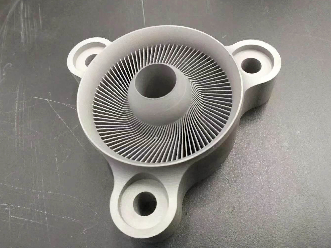
Yes — a 3D printed manifold can go on the dyno when three conditions are met. It needs a 1.0 mm minimum wall, stress relief after support removal, and machined sealing faces at Ra 1.6 µm. The dyno does not care how the part was made; it cares whether the flange seals and the wall holds its shape through the heat cycle.
What does dyno use demand from a printed manifold?
A dyno run is a short, high-load thermal cycle. The manifold sees hot exhaust gas, a cold inlet charge and cell vibration, so it has to seal at the flange while the metal moves under the temperature change.
Printed stainless handles that window well. The wall is the main variable: 1.0 mm is enough for a short run at moderate boost, and 2.0 mm is used where the runner carries the flange load. Stainless steel 3D printing keeps both options in one build.
The failure to watch is flange movement, not bulk strength. A thin flange with no relief can bow after the first heat cycle and open a leak path, which is why relief and machining are scheduled before the first pull. The cell adds its own loads as well: a manifold clamped to a rigid dyno frame sees the frame's stiffness, not the engine's, so a part that survives the bench may still need a different support strategy in the vehicle.
The process family and its terminology follow ISO/ASTM 52900; the 316L powder datasheet supplies the expansion and relief data used for the cycle. Thermocouple bosses and pressure taps can be welded to the printed body before the run, which is often why a printed prototype is chosen for a first test; a welded part should come from a known powder lot.
Which checks must pass before the first pull?
Three checks, in order:
Measure the wall on the slice model and reject anything below 1.0 mm.
Relieve at 850 °C for 1.5 h after support removal, then re-datum within 24 h.
Machine the sealing faces to 0.05 mm flatness and Ra 1.6 µm, and check them before assembly.
A part that passes all three can be bolted to the cell with a standard gasket. A part that fails any one is not a dyno part, whatever the print looked like. Wall measurement is done on the slice model before the build and again on the finished part at the flange and runner sections; a wall that measures 1.0 mm on the model can read 0.9 mm after blasting if the surface removal is not accounted for. The pass/fail is recorded against the drawing, not against the print file.
The stress relief cycle and the machining step are planned together. The cut then follows the datum that the relief leaves.
Where does the printed part stop being suitable?
The boundary is thermal and pressure-related, not cosmetic. For continuous exhaust temperatures above roughly 600–800 °C, the material choice moves to a nickel-based superalloy; the printed stainless part is for short validation runs, not for a hot-end duty cycle.
It also stops being suitable when the manifold is a certified pressure boundary, when the program needs a material certificate with full traceability, or when the run is meant to prove durability rather than function. Those are different tests with different parts.
The dyno gives a functional answer for the geometry and the seal. It does not certify the part, and it does not replace a durability program. For a durability program the part would be built from a certified powder lot with a full test coupon set, which is a different procurement than a prototype, and the boundary is written down before the build so the test plan matches the part.
Send the drawing, the boost target and the run duration to Neway; we will confirm the wall, the relief cycle and the flange finish before quoting the build.
.webp)