How precise can EDM machining be for 3D printed components?
How precise can EDM machining be for 3D printed components?
EDM precision on a 3D-printed component is the smallest feature tolerance that a defined wire or sinker route can repeatedly demonstrate after finishing, unclamping, cleaning, and measurement. It is not the smallest command increment shown on the machine and it is not one universal micron value. Spark gap, wire or electrode wear, flushing, taper, thermal drift, workholding, printed residual stress, porosity, allowance, and measurement uncertainty all contribute. A tolerance such as ±0.01 mm may be a reasonable starting RFQ discussion for some accessible features, while a much tighter target requires a geometry-specific process study. The precision EDM review should define the feature and evidence.
Resolution, Accuracy, and Repeatability
Resolution is the smallest commanded or displayed movement. Accuracy is closeness to nominal. Repeatability is the spread of repeated results. Tolerance is the drawing limit. These properties should not be substituted for one another. A machine with fine axis resolution can still miss a printed feature because thermal drift, wire deflection, electrode wear, fixture distortion, or spring-back is larger than the commanded movement.
The inspection system has its own error. State the CMM, optical system, microscope, profilometer, gauge, calibration status, temperature, stabilization time, datum construction, probe or optical method, sample count, and uncertainty. ISO 230-2 may provide a reference for machine-tool positioning evaluation, while ISO 14253-1 can help structure a conformity decision when uncertainty approaches the tolerance boundary. These references organize evidence; they do not qualify an unknown printed geometry.
Precision is produced by the relationship between the commanded path and the electrical gap. Discharge energy, wire or electrode deflection, wear compensation, flushing, taper, thermal drift, and workholding can move the final boundary away from the nominal path. The printed state adds residual stress and porosity, so the component may move when stock is removed or the fixture is released. Measure the feature in the final state instead of treating machine resolution as a finished-part result.
Access and Final-State Control
Precision on a printed component is a relationship between the programmed path, the electrical gap, and the final measurement state. Wire tension, electrode wear, flushing, taper, thermal drift, workholding, and printed residual stress can move the finished boundary. If polishing, coating, or heat treatment follows EDM, the final tolerance must include stock removal or added thickness. For a feature that controls an aerospace load path, qualify the actual geometry and material lot before treating a small number on a machine screen as a production limit.
Wire and Sinker Precision
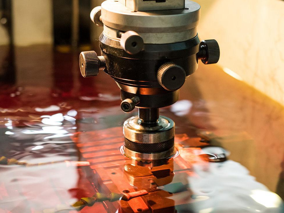
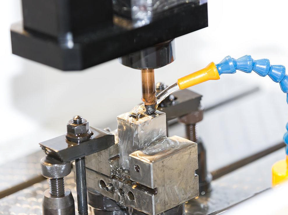
Wire EDM can provide a controlled profile when the wire has a start route and the part is supported. Wire tension, guide alignment, pass count, taper, flushing, workpiece height, and wall stiffness influence the result. Sinker EDM can provide a controlled cavity when the electrode form, wear compensation, orbiting, flushing, and corner access are stable. The floor and sidewall of a deep pocket may need separate inspection. The final dimension also depends on whether polishing, coating, or heat treatment follows.
For a thin aerospace contour, choose wire EDM when the conductive profile is accessible and low cutter force controls the risk; verify profile, position, recast, and the unclamped state. For a tooling cavity, choose sinker EDM when the shaped electrode reaches the feature; verify floor, sidewall, corners, roughness, and final dimensions. For a medical-development part, define contact, cleaning, sterilization, and approval conditions before accepting a precision claim; this remains a project-specific development qualification, not clinical approval or a substitute for regulatory evidence.
Use the surface-treatment route only after the EDM state, allowance, and inspection condition are recorded. A polishing or coating step can change a small feature, and the final report must distinguish the as-EDM result from the finished component. For aerospace, medical development, and tooling alike, the project owner should approve the complete sequence before release.
Because the discharge gap is affected by wire position, electrode wear, flushing, and thermal drift, the same nominal tolerance can require different controls on a thin rib and a deep cavity. Record the route, final state, and measurement uncertainty. A surface-treatment review is also needed when polishing or coating follows EDM, because added thickness or stock removal can change the accepted dimension. For a fatigue-sensitive component, add recast or HAZ evidence before release.
RFQ and Acceptance
Provide CAD and drawing revision, datum scheme, tolerance by feature, material grade and lot, build orientation, heat-treatment state, wall thickness, access, allowance, quantity, roughness, recast or HAZ limit, functional requirement, inspection temperature, and decision rule. Request the wire or electrode plan, parameter family, workholding method, calibration record, measurement uncertainty, dimensional map, and nonconformance disposition.
Use a representative feature or coupon when the geometry is unfamiliar, but match its thickness, orientation, access, and material state to the component. Measure after unclamping and after all dimension-changing operations. A two-micron target should remain a development target until repeated evidence on the final part supports it. The precise EDM result is the traceable tolerance the component can demonstrate, not a number detached from process and measurement conditions.
Before approving this application route, check the electrical discharge machining edm against the part's operating condition, critical feature, and acceptance limit.
For supplier comparison, use the CNC machining service to separate a process capability statement from evidence on the completed part.