
Machining Stock Allowance: How Much Should Stay?
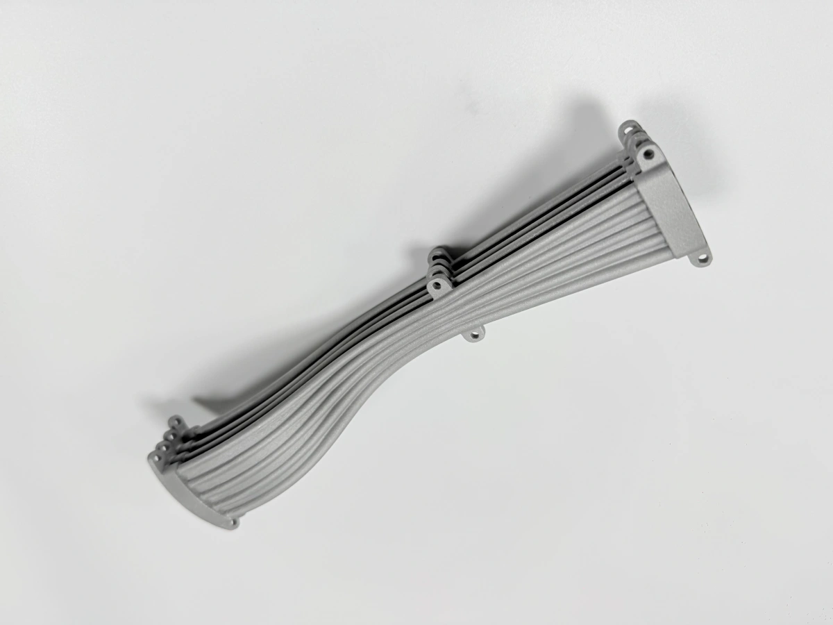
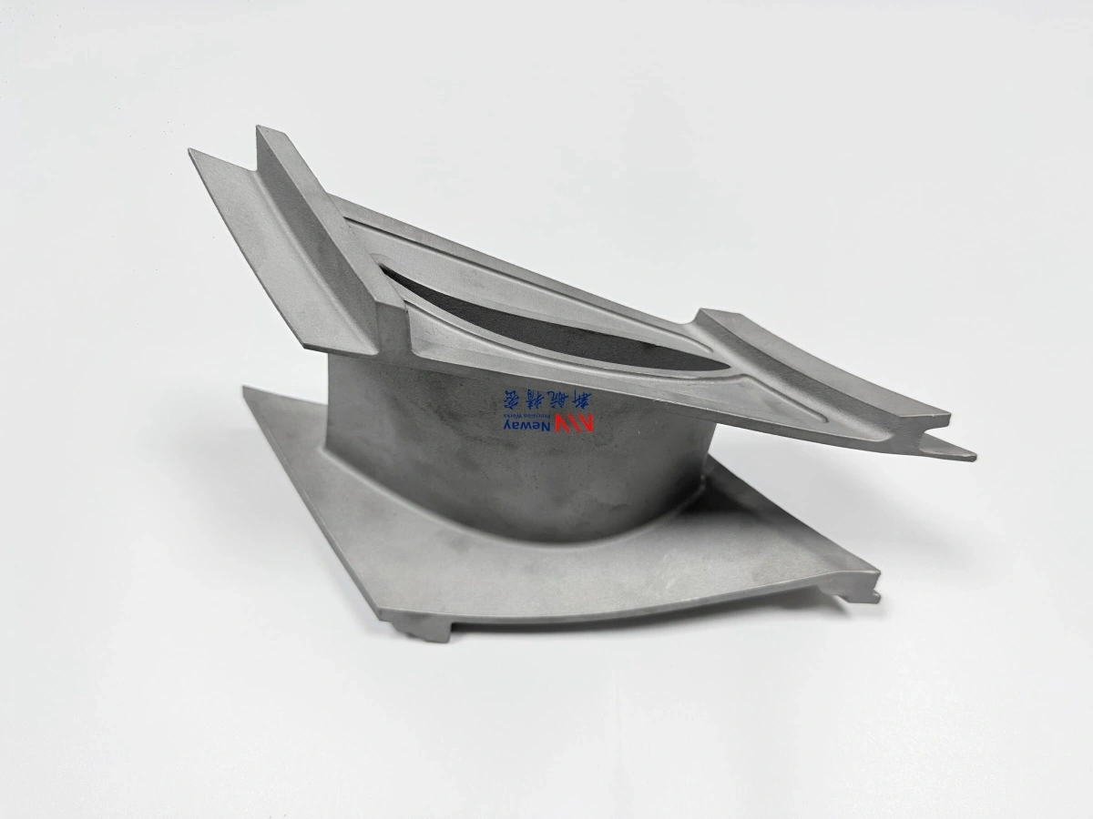
Machining stock allowance on a printed liner is 2.0 mm on the assembly faces and 1.0 mm in the holes. The allowance covers the two thermal cycles before the cutter and leaves enough metal to cut a clean face; less than that and the part is scrap before the finish pass. A zero-stock print looks economical until the first scan.
How much machining stock allowance should each face carry?
Faces carry 2.0 mm and holes carry 1.0 mm, because the faces are cut in one setup and the holes are drilled and tapped after. The face allowance covers flatness, warp and the datum cut. The hole allowance covers position, which moves with the thermal cycles and with stress released by the face cut. It also has to survive the springback after each cut, which is why roughing never goes to final size.
The allowance is not uniform. Small windows and ribs move less than the long open wall, so 2.0 mm is a minimum across the part, not a target. A local area that prints 1.6 mm from nominal is already at the edge and needs a second look at orientation.
The datums are cut first, and that cut takes about 0.3 mm off the base plate. The 2.0 mm face stock has to cover that cut plus the 0.05 mm flatness and the local warp, or the datum ends up in the print skin. If the plate is cut to final size before the holes, the hole positions move with the released stress.
Why do two thermal cycles eat the allowance?
Solution treatment at 1,180 °C for 1 h and hot isostatic pressing at 1,180 °C and 100 MPa for 3 h both move the part. Solution treatment releases printing stress; HIP closes porosity and creeps the wall under pressure. Together they can move the blank by up to 0.5 mm, which is why the machining stock allowance is measured from the post-HIP scan, not from CAD.
The two cycles are separate measurements. The first scan brackets HIP and shows how much the heat moved; the second is the final full scan. If the two are compared without the blank scan in between, the cutter gets blamed for movement that happened in the furnace.
Allowance also changes with orientation. A part built on its base plate has stock on the window faces; a part built on its side has stock on the flange. HIP creep follows gravity, so the scan comparison has to be read against the build direction. A blank that prints 0.4 mm high at the flange and 0.1 mm low at the windows needs a different allowance per region, not one number for the whole part.
When is more stock the wrong answer?
More stock is the wrong answer when the extra material changes the heat treatment response. A thick pad of stock heats and cools more slowly than the 1.8 mm wall, and the gradient becomes a distortion source of its own.
It is also wrong when the part is small enough that the extra mass changes the build. A liner with 4.0 mm face stock needs a longer build, more powder and a heavier post-build cut, and the extra 2 mm does not buy a better face. Thicker stock also costs machining time, because every extra millimetre of face stock is a full roughing pass on a nickel alloy that work-hardens.
The practical ceiling is about 3.0 mm on faces. Beyond that, the stock has to be removed in a second roughing setup, and the part is handled twice for no gain. When the drawing allows it, 2.0 mm faces and 1.0 mm holes are enough for a liner of this size.
Send the drawing with the stock callout and the heat treatment sequence. We will confirm the allowance against the scan, name the datum cut, and quote the CNC machining and superalloy printing steps together. One review covers stock, heat treatment and inspection.
.webp)