
M4 Thread in a Thin Wall: How Do You Tap It?
M4 threads in a thin wall are cut, not printed. A 3.3 mm pilot hole is drilled and tapped at 250 r/min to 1.5×D, then checked with go/no-go gauges. The wall is GH3536, the thread is small, and tapping is where a printed liner most often gets scrapped. A printed thread in the same wall would arrive undersized and partly filled.
Why tap an M4 thread in a thin wall?
A printed M4 thread in a thin wall does not hold tolerance, because the melt pool cannot resolve a 0.7 mm pitch on a 4 mm diameter. The crests arrive rounded, the root is partly unfused, and the flank angle wanders along the helix. Tapping removes that uncertainty by cutting the thread into solid metal.
Tapping also gives a clean start. A printed thread starts on a rough, sometimes overhanging face, and the first turn decides whether the bolt goes in square. A tapped hole has a chamfer and a controlled minor diameter, so the bolt starts where the drawing says.
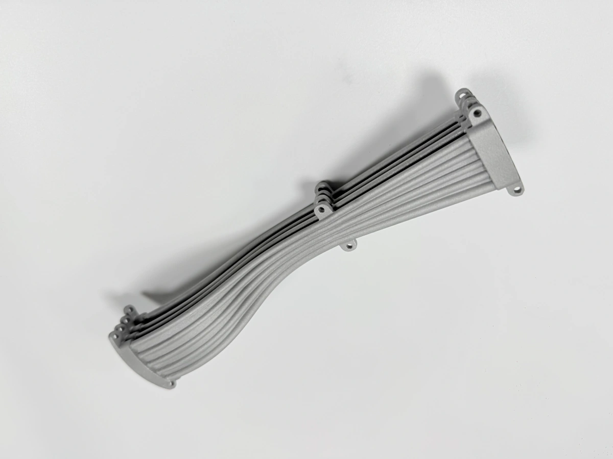
Printing the thread does save one operation, and that matters on a large batch. On a single liner with 12 M4 holes, the setup for tapping is already there for the Ø12 holes and the flange, so the saving is small against the risk of a scrapped part. The superalloy printing route already sets the wall and the local boss, and tapping follows it.
What pilot hole and speed avoid tearing?
The pilot hole is 3.3 mm and sits in the local boss around each hole, where the wall thickens to carry the thread. Drilling and tapping happen in the same setup as the flange, so the hole position comes from the datum, not from the printed skin.
A 0.05 mm position error at the hole becomes a 0.05 mm error at the bolt. The hole is spotted with a stub drill before it is opened to size, because a long drill walks on the curved wall.
Speed is 250 r/min with a feed of 175 mm/min, which is 0.7 mm per revolution and matches the M4 pitch. A faster tap tears the flank in a nickel alloy; a slower one work-hardens the surface before the cut starts. Cutting oil is flood, not mist, because the chip has to clear a hole only a few millimetres deep. Chips are cleared every few turns, and the hole is blown out before the tap enters.
The tap is a machine tap with a spiral flute, and it is replaced on a count, not on failure. A worn tap cuts oversize and pulls the thread off centre, and the go gauge then enters too far. Every part is checked with go/no-go gauges: the go gauge passes, the no-go does not.
When should the thread become an insert?
An insert is the answer when the wall cannot carry the thread, which means a local thickness below about 3 mm around the hole. It is also the answer when the part will be assembled and disassembled more than a handful of times, or when the thread is a jacking point.
A tapped M4 in a thin wall has roughly 1.5×D of engagement, which is enough for a static cover but not for repeated torque. A helicoil or a key-locking insert spreads the load over a larger diameter and can be replaced without scrapping the liner.
The insert also changes the drilling sequence. The hole is drilled and tapped for the insert, not for the bolt, and the insert is installed after heat treatment and cleaning. That adds one operation and one inspection step, and it is cheaper than a failed thread on a finished part.
Send the hole pattern, the local wall thickness and the assembly torque. We will propose the pilot size, the tap and the insert option, and quote the CNC machining step with the thread inspection. One review covers drilling, tapping and gauging, and names the thread class.
.webp)