
How much damage does sampling for metallographic analysis cause to the part?
Yes, metallographic sampling is destructive because the part or coupon must be sectioned, mounted, ground, polished, and often etched to expose its microstructure. The damage can be limited and documented when the sampling location, orientation, geometry, material, process route, and final condition are agreed in advance. A section from a functional part is not automatically representative of the whole part, and the method does not replace non-destructive inspection. For an RFQ, provide the drawing revision, critical feature, sacrificial allowance, lot, heat-treatment state, acceptance question, and report requirement.
Understanding the Scope and Nature of Damage
The physical impact is usually localized to the selected cut and preparation area, but cutting can remove material, interrupt a surface, or make the component unusable. Decide whether to sample a witness coupon, a qualification article, or the production part before work begins. Record the cut plan, datum, orientation, sample identity, and chain of custody so the micrograph remains tied to the correct build.
Nature of Sampling Damage:
Localized Destruction: The process involves removing a small, specific section from a component or building a dedicated test coupon alongside production parts.
Irreversible Alteration: The sampled section is destroyed during cutting, mounting, polishing, and etching. It cannot be returned to service.
Controlled Sacrifice: This is a deliberate trade-off where a small portion is sacrificed to verify the structural integrity, heat treatment efficacy, and manufacturing quality of the entire lot or critical region.
Quantifying the Impact: Quantify the sampling impact by documenting the removed volume, cut location, remaining dimensions, surface condition, and whether the specimen is a dedicated witness coupon or a production part. The section plan should state whether the evidence comes from a witness coupon or a customer-owned production part.
For destructive testing, we typically use dedicated witness coupons that are built simultaneously with the production parts, using identical parameters and material batches. This approach preserves 100% of the functional components.
When sampling from an actual component is necessary (for failure analysis or first-article inspection), we remove the absolute minimum volume required—typically just a few cubic centimeters, depending on the feature size being examined.
Strategic Determination of Sampling Locations
Sampling should follow the engineering question rather than a convenient location. Use the build orientation, stress path, wall transition, support contact, channel, and suspected defect location to choose the section. Compare as-built, heat-treated, HIP-treated, and machined states separately, then verify that the section represents the material and process condition under review.
1. Standards-Based and Critical Area Focus
Following International Standards:
ASTM E3 and E407 guide specimen selection for metallographic preparation.
Aerospace Standards (such as NADCAP AC7114) specify location requirements for critical components, particularly those for Aerospace and Aviation applications.
Critical Region Identification:
High-Stress Areas: Locations identified through finite element analysis (FEA) as experiencing maximum stress during service.
Geometric Transitions: Areas near holes, corners, and thickness changes where stress concentrations and microstructural anomalies are most likely to occur.
Support-Contact Regions: For parts built using Powder Bed Fusion, we examine areas adjacent to support structures where thermal history differs significantly.
2. Manufacturing Process-Driven Sampling
Build Orientation Considerations:
Samples are extracted to examine microstructures parallel and perpendicular to the build direction, assessing anisotropy.
For Titanium Alloy components, we specifically examine the effect of Heat Treatment on transforming acicular martensite into equilibrium phases.
Process-Specific Defect Monitoring:
Lack-of-Fusion Detection: Locations where layer-to-layer adhesion might be compromised.
Heat-Affected Zone Analysis: For components undergoing subsequent Hot Isostatic Pressing (HIP), we verify pore closure and grain boundary healing.
3. Multi-Technique Correlation Approach
A correlated plan can reduce unnecessary sacrifice. Use CT or another non-destructive method to locate a region, then select a representative section when the microstructure or phase evidence is needed. Non-destructive data guide the decision but do not make a destructive sample representative by themselves. Approve the cut, record the limitation, and define the disposition before sectioning.
Non-Destructive Guidance:
CT Scan Data: Initial non-destructive testing identifies regions of interest for targeted metallographic sampling.
Ulasonic Testing: Detects internal anomalies that warrant microstructural verification.
Witness Coupon Strategy: For high-value components such as those in Medical and Healthcare implants or Automotive safety systems, we employ witness coupons that:
They are built simultaneously with production parts
Experience an identical thermal history
They are positioned in challenging locations within the build volume
Can represent the entire build batch
Industry-Specific Applications and Damage Mitigation
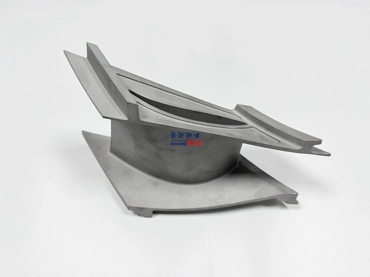
Aerospace Component Validation: For Superalloy 3D Printing components like turbine blades from Inconel 718, we sample to verify:
Grain size and orientation after solution treatment
Carbide distribution along grain boundaries
Presence of deleterious phases after long-term exposure simulation
Medical Device Certification: For Ti-6Al-4V ELI (Grade 23) medical implants, sampling should cover the material specification, sample location, final condition, and required chemistry or microstructure evidence. Project-level medical-device qualification and biocompatibility review remain separate from metallography.
Biologically critical surfaces and interfaces
Regions adjacent to porous structures for bone integration
Assessment of alpha-case formation before and after Surface Treatment
The final report should identify the sample, location, orientation, preparation sequence, material and lot, process and final state, microstructure observations, measurements, images, standard, uncertainty or limitation, reviewer, and disposition. If a customer-owned part is affected, obtain approval before cutting. The result supports a defined acceptance or investigation decision; it does not automatically certify the remaining geometry.
.webp)
