Are there size or geometry limitations for parts undergoing HIP for density enhancement?
Are There Size or Geometry Limitations for Parts Undergoing HIP for Density Enhancement?
Overview
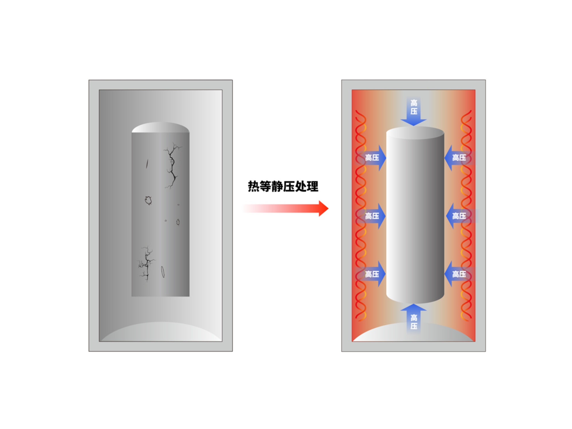
Hot Isostatic Pressing (HIP) is a highly effective post-processing method for enhancing the density and mechanical performance of 3D printed metal parts. However, like all thermal-pressure processes, HIP has practical limitations based on part size, geometry, wall thickness, and internal features. Understanding these constraints is essential for part design and production planning.
Key Size and Geometry Limitations in HIP Processing
1. Maximum Part Size
HIP is performed in sealed, high-pressure vessels with fixed chamber dimensions. The size limitation is directly tied to the equipment's working envelope.
Typical commercial HIP units support parts up to 500–1000 mm in diameter and 1000–1500 mm in height
Very large parts may require custom HIP tooling or be segmented and post-welded
2. Wall Thickness Considerations
Thin-walled structures (less than 1.5 mm) may deform or collapse under HIP conditions due to:
Uneven wall stress distribution
High isostatic pressure (100–200 MPa) and temperatures (900–1250°C)
Recommended:
Maintain uniform wall thickness >2 mm
Avoid sharp transitions or unsupported surfaces
3. Internal Channels and Enclosed Cavities
HIP is effective only if the internal porosity is fully enclosed. Open internal channels or interconnected voids exposed to the atmosphere can:
Prevent uniform pressure transfer
Trap argon or gases, resulting in unbalanced densification or collapse
Solutions:
Seal openings or add sacrificial closures before HIP
Use canister encapsulation for complex internal geometries
4. Large Aspect Ratios
Parts with extreme aspect ratios (e.g., long thin rods or tall hollow cylinders) may:
Experience bowing or bending under thermal stress
Require special fixturing or support jigs to maintain straightness
Best practices:
Keep L:D ratio under 10:1 when possible
Use symmetric designs to reduce deformation risks
5. Material-Specific Behavior
Some materials are more prone to geometric distortion than others:
Ti-6Al-4V: generally stable, minimal distortion
Tool Steel H13 and SUS316L: require slower cooling rates to reduce warping
Inconel 718: performs well but can deform in unsupported overhangs
Summary of HIP Design Guidelines
Limitation | Recommended Strategy |
|---|---|
Max part size | Confirm chamber dimensions (≤1000 mm typical) |
Thin walls | Keep thickness ≥2 mm, add ribs if needed |
Internal cavities | Ensure they are closed or encapsulated |
Long parts | Minimize aspect ratio or use fixturing |
Complex geometries | Use symmetrical designs, support critical features |
Recommended Services for HIP-Compatible Design
Neway 3DP ensures successful HIP outcomes through:
Design for HIP Manufacturing Expert support for wall thickness, geometry, and part closure strategies
Hot Isostatic Pressing Precision-controlled densification for high-performance applications
CNC Machining Post-HIP dimensional refinement to meet final tolerance requirements