
What is the typical reduction in surface roughness achievable with HIP?
What is the typical reduction in surface roughness achievable with HIP?
There is no responsible universal percentage or fixed Ra reduction for HIP-treated 3D-printed parts. HIP is designed primarily to reduce suitable internal porosity, while external roughness is governed by layer geometry, partially fused particles, support removal, machining, powder condition, coating, and measurement method. A part may show a small profile change after densification, but the size and direction are material- and geometry-specific. Set a baseline and a project target, then verify the final surface after the last operation that can change it.
Why No Fixed Number Applies
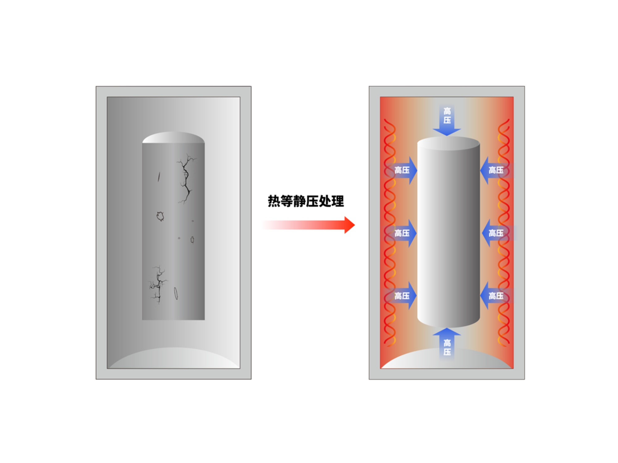
Surface roughness is a sampled profile, not a direct measurement of all surface condition. Ra, Rz, Rq, waviness, form, pits, and open pores can tell different stories. HIP can reduce a closed subsurface void because pressure and heat promote creep and diffusion. It does not provide the same material-removal action as machining or polishing, so a layer stair-step or adhered particle may remain. The result depends on whether the measured trace crosses an affected pore, whether the surface is open to the atmosphere, and whether a later operation changes the profile.
Measurement setup also changes the apparent reduction. A stylus direction parallel to the layers can produce a different value from a direction across them. Cutoff, evaluation length, filter, tip radius, optical focus, threshold, and surface cleaning affect the result. If the pre-HIP part is measured with residue and the post-HIP part is cleaned and polished, the reported change is a combined cleaning and finishing effect. Document the method and the final state before comparing numbers. The final state must include any heat treatment, machining, coating, and cleaning that the buyer will receive.
A useful comparison preserves the material lot, build orientation, section, cleaning method, and final condition. Measure representative external traces and inspect the location of any internal indication before HIP, after HIP, after machining, and after polishing. If the value is below the instrument's repeatability or the location cannot be reproduced, report the result as unresolved. Do not convert a visual improvement into a percentage without a baseline, target, uncertainty, and stated measurement direction. Record the operator, instrument calibration, measurement temperature, and trace location so another inspector can reproduce the comparison.
Set a Defensible Target
Start with the function. A seal land may need a roughness and form limit; a bearing surface may need roughness, roundness, hardness, and edge control; a flow passage may need pressure drop, wall thickness, and cleanliness; a cosmetic face may use a visual standard. Choose HIP only when an internal defect is relevant to that function. For an Inconel 718 bracket, use CT or metallography to establish whether internal porosity is the fatigue risk, then machine and measure the mating surface. For a 316L manifold, pair surface measurement with cleaning, wall thickness, flow, and leak evidence.
Write the target as a measured criterion rather than a marketing promise. Specify the acceptable roughness range, trace locations, direction, cutoff, sampling count, instrument, uncertainty, and surface state. ISO 21920 may be invoked for profile parameter reporting. If the target is unknown, mark it as an engineering-development value and do not present a typical reduction as an acceptance limit. A target can be a range or maximum only after the drawing, service interface, and measurement capability are aligned.
Verification Sequence
Measure representative locations before HIP, after HIP, after rough machining, and after final finishing. Keep the same material lot, build orientation, geometry, measurement direction, cleaning condition, and instrument where the purpose is to isolate the HIP effect. Use CT or metallography for internal indications, a profilometer or validated optical method for external roughness, CMM or scan for form, and leak or flow testing for a functional passage. State resolution, uncertainty, trace count, and acceptance decision in the report.
For a deep channel, a surface trace at the opening does not prove the entire internal wall is smooth. Use a method that can reach or infer the controlling feature, and pair it with flow or pressure evidence when appropriate. For a thin flange, inspect edge roll and flatness after restraint is removed. For a polished insert, measure after polishing and cleaning. If the final surface fails while internal porosity passes, the correct action is surface rework or a design disposition, not a claim that HIP was ineffective at densification.
RFQ and Boundary
Provide CAD and drawing revision, material and lot, additive route, orientation, initial surface state, target roughness and form, functional interface, suspected internal defect, HIP specification, subsequent heat treatment, machining and polishing allowance, measurement method, sampling, quantity, and acceptance authority. Request before-and-after surface and internal data, cycle records, dimensional maps, calibration, and deviations. HIP can improve a surface-related outcome only when the relevant defect and final measurement support it; it does not supply a universal roughness reduction. Release the final measured surface and functional result.
If this question concerns a failure mechanism, compare the HIP processing service after the suspected cause and test condition are identified.
For a controlled production decision, request the surface-treatment service when the final state and deviation path need traceable evidence.
.webp)
