SLM Manufacturing Readiness for Metal AM Purchase Order Release
An SLM manufacturing purchase order should not be released only because a STEP file can be printed. For metal AM parts, the PO must freeze the finished-part expectation: which features stay as printed, which surfaces require CNC, which supports are acceptable, which post-processing steps are required, and which records will be used for receiving inspection. If these points are left open, the supplier may quote a buildable blank while the buyer expects a finished industrial part.
Neway reviews powder bed fusion 3D printing service orders from the PO-release side. The question is whether the engineering, purchasing, and receiving teams can all read the same documents and understand the same route. A release package that works for conventional machining often needs extra AM details because build orientation, support contact, residual stress, and post-build finishing are part of the manufacturing decision.
This article explains what to lock before releasing SLM metal 3D printing work. It is useful when a prototype has been approved, when a pilot lot is moving into repeat purchase, or when a precision metal additive manufacturing part has functional surfaces that cannot be treated as raw printed geometry.
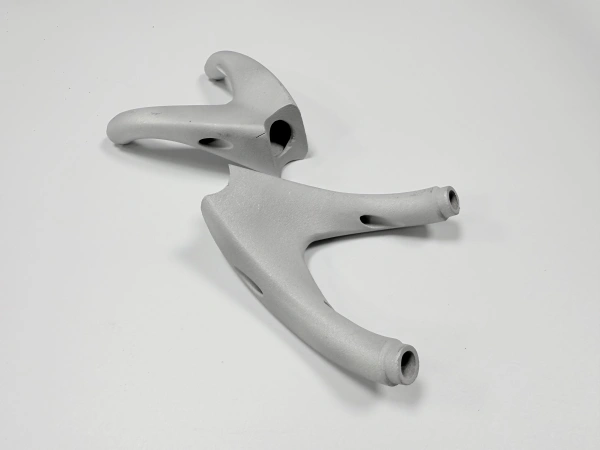
SLM Inputs That Should Be Frozen Before Build Release
The first release item is the geometry baseline. A neutral CAD file is needed for build preparation, but the 2D drawing controls the finished condition. Revision level, material grade, quantity, service category, and application environment should match across the PO, drawing, and quote. If the buyer sends one material in the email and another material on the drawing, the build cannot be released cleanly.
SLM additive manufacturing also needs decisions that are not visible in a machining-only PO. Build orientation affects support location, stair-step direction, surface exposure, thermal history, and machining allowance. Support contact may be acceptable on a non-functional underside, but it may be unacceptable on a sealing face, airfoil-like profile, internal passage opening, or visible assembly face. These limits should be frozen before the nesting and build file are prepared.
Material condition is another release point. Some metal AM parts are ordered as printed and stress relieved; others need heat treatment, HIP, CNC machining, EDM, blasting, polishing, or coating. If the PO only says "SLM part," the supplier may not know whether the purchase covers a printed blank or a finished assembly-ready component.
Orientation-Sensitive Faces That Need Engineering Review
For SLM metal 3D printing, not every surface reacts the same way to orientation. Down-facing surfaces usually carry more support risk. Tall thin walls can be sensitive to thermal stress and distortion. Broad flat faces may move after stress relief or after support removal. Internal channel outlets can be affected by powder escape and surface cleanup. A buyer releasing a PO should identify which of these surfaces are functional instead of assuming the build direction is a supplier-only choice.
We ask whether the most important surface controls flow, fit, load transfer, sealing, alignment, or inspection. A non-critical cover surface can often tolerate a more practical build orientation. A machined mounting face, bearing seat, threaded boss, datum pad, or fluid interface usually cannot. If the drawing has GD&T, the datum scheme should be reviewed against likely support contact and machining access. The PO should not leave the datum strategy to guesswork.
Orientation can also change cost. A taller build may use more machine time. A support-heavy orientation may add removal labor and increase cleanup risk. A different orientation may protect a critical face but require more CNC stock. The lowest raw build price is not always the lowest finished-part price, especially when the PO includes inspection and post-processing.
When Support Removal Becomes a Delivery Item
Support removal is often treated too casually in SLM manufacturing orders. For simple brackets, supports may be removed and blended without much discussion. For precision hot-section hardware, hydraulic manifolds, medical tooling, robotics components, or compact aerospace fixtures, support removal can become a named delivery item. The support location, removal method, remaining witness marks, and protected surfaces all affect acceptance.
A support mark on a later-machined pad is usually less risky than a support mark on an as-printed flow surface. A support inside a narrow cavity may be unacceptable if access is limited. A support near a thin rib can damage the rib during removal. If EDM is required to separate a part from the build plate or to protect a delicate feature, that operation should be included in the route and not discovered after printing.
Buyers can make the PO clearer by naming no-support zones, surfaces that may be machined after removal, and features that must remain as printed. Where support scars are acceptable, the drawing can state the area or functional boundary. Where they are not acceptable, the supplier needs time to adjust orientation or discuss a design change before the build starts.
Release item | Why it matters before SLM build | Risk if missing | Owner before PO |
|---|---|---|---|
Drawing revision and STEP revision | Locks the geometry and finished requirements used for build preparation | Supplier may quote or print from mismatched data | Buyer engineering |
Material and final condition | Separates printed blank, stress-relieved part, HIP part, and machined finished part | Post-processing cost and acceptance scope may be omitted | Buyer and supplier engineering |
Critical orientation-sensitive faces | Identifies surfaces affected by supports, stair-step direction, or distortion | Build direction may protect the wrong surface | Buyer design owner |
No-support zones | Prevents support contact on sealing, flow, visible, or fatigue-sensitive surfaces | Removal marks may remain on functional geometry | Buyer design owner |
CNC or EDM scope | Defines which dimensions cannot rely on as-printed surfaces | Finished features may be priced as optional or missed | Buyer purchasing and supplier manufacturing |
Inspection record package | Connects drawing risk to receiving evidence | Receiving may ask for records after the part is complete | Buyer quality team |
Drawing Notes That Separate Printed and Finished Features
A useful SLM drawing separates as-printed surfaces from finished surfaces. It does not need to over-control every texture or minor edge. It should mark the surfaces that need CNC machining, reaming, tapping, EDM, polishing, coating, or special inspection. This separation helps Neway quote the real work and helps purchasing compare offers on the same basis.
Some features should not be left as printed unless the design owner accepts the risk. Threads, close-fit bores, sealing faces, bearing seats, flat mounting pads, and controlled datum surfaces are typical examples. Internal passages are different: they may not be reachable by normal cutting tools, so inspection may rely on flow checks, visual access, CT review, or buyer-defined acceptance methods depending on the part function.
Post-processing sequence should also be visible enough for PO release. Heat treatment may be needed for stress relief or material condition. HIP may be discussed when internal density and fatigue-sensitive use are part of the acceptance risk. CNC machining usually belongs after thermal steps when final dimensions depend on stable geometry. The exact route depends on the drawing and material review, but the PO should not hide these steps in a single phrase.
PO Attachments That Reduce Quote Rework
A release package for SLM additive manufacturing should include the STEP file, controlled 2D drawing, material grade, quantity, finish state, critical features, machined surfaces, post-processing notes, inspection requirements, and target delivery window. For repeat purchase, it should also include the approved prototype revision or any change notes since the last build. This prevents a pilot-lot approval from being treated as a new and uncertain part every time.
If the part is still in development, the PO should identify what is fixed and what is open to DFM feedback. For example, a prototype may allow support marks on a non-functional surface while the next lot requires a cleaner exterior. A hydraulic or cooling part may need powder removal discussion before the channel geometry is frozen. A bracket may need additional machining stock around a datum pad if distortion is expected after support removal. These choices affect the quote before the first layer is built.
When a part is not ready for SLM release, Neway may recommend a drawing update, a different orientation review, a simplified prototype scope, or a switch to CNC for simple geometry. A plate, shaft, spacer, or flange with no AM-driven geometry may be more practical by machining. SLM becomes worth reviewing when part consolidation, internal channels, weight reduction, hard-to-machine material, or low-volume complexity justifies the added build preparation and post-processing.
Information Needed for a Controlled Release
To receive a reliable quote and release a manufacturable PO, send CAD or STEP data, a 2D drawing, material grade, order quantity, prototype or repeat-lot status, application environment, surfaces that must remain free of supports, surfaces needing CNC or EDM, heat treatment and HIP expectations, surface finish requirements, inspection records, and any receiving documents required before shipment. If the drawing contains tight GD&T or internal channels, highlight the features that control function.
The strongest SLM manufacturing PO is not the longest one. It is the one that tells the supplier what must be printed, what must be finished, what must be protected, and how the buyer will accept the part. That clarity reduces quote revisions, protects functional surfaces, and gives both teams a practical route from build release to finished inspection.
Related FAQs